DESCRIPTION
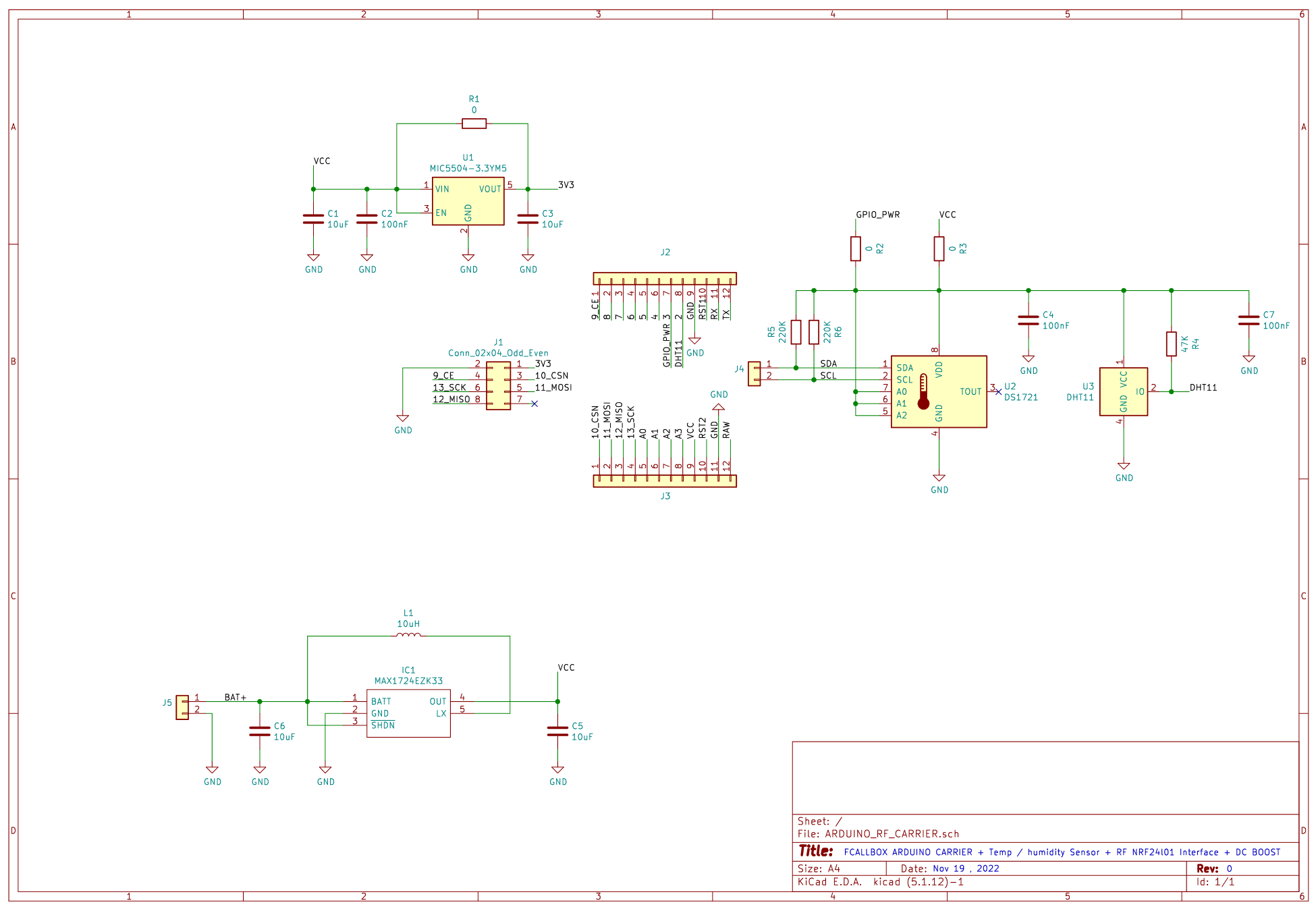
This board is a carrier board for Arduino Pro mini, it allows the assembly of the parts following :
Arduino Pro mini
RF board: NRF24L01 + 2.4GHz Wireless RF Transceiver
Temperature sensor DS1721 -55°C à +125°C with precision 0.0625°C
Humidity sensor DHT11 20 to 80% (relative humidity) +/-5%
Battery power option, with a boost Max1724 (0.8V to 3.3V)
Regulator LDO 5V to 3.3V option, in case of 5V powering and NRF24L01 which supports only 3.3V
The main application is a temperature and humidity sensor with Radio link, it is used in the FCALLBOX Main server
Sommaire
SCHEMATIC

Download here the schematic in PDF format
BOM
Option POWER 5V or 3V3
If power is 5V : do not populate R1, the power is then in 3.3V (important for NRF24L01)
If power is 3.3V : populate R1 only
Top view
| Ref |
Description |
Manufacturer / reference |
| R1 |
Resistor 0R 5% 0603 |
All brands |
C1,C3 |
Capcitor 10uF 10V 10% X5R 0603 |
All brands |
C2 |
Capacitor 100nF 25V X7R 10% 0603/TD>
| All brands |
U1 |
Regulator LDO 3.3V 500mA SOT23-5/TD>
| SPX3819M5-L-3-3 or MIC5504-3.3YM5-TR |
|
Option Boost for battery operation
Top view
| Ref |
Description |
Manufacturer / reference |
| L1 |
inductor 10uH 300mA min 1812 |
All brands |
C5,C6 |
Capacitor 10uF 10V 10% X5R 0603 |
All brands |
IC11 |
DC/DC boost 0.8V to 3.3V |
MAX1724EZK33 |
|
Temperature and humidity sensors option
To view
| Ref |
Description |
Manufacturer / reference |
| R2,R3 |
Resistor 0R 5% 0603 |
All brands |
| R4 |
Resistor 47KR 5% 0603 |
All brands |
| R5,R6 |
Resistor 220KR 5% 0603 |
All brands |
C4,C7 |
Capacitor 100nF 25V X7R 10% 0603/TD>
| All brands |
U3 |
Humidity sensor DHT11 |
DHT11 |
U2 |
Temperature sensor DS1721 |
Maxim (DALLAS Semi Conductor) |
|
PCB
The board has 48x20mm dimension
Download here the manufacturing files
Assembly
La carte de dimensions 48x20mm

Download here the assembly drawing in PDF format
Cabling Sensor based on NRF24L01 without PA
Pictures
|
Arduino on carrier
Remove the 2 leds and the rebulator on the red circles to decrease the consumption

|
Modification to control RF module power
To reduce the consumption at minimum,do not mount R2 and add a PNP MMBT5401 and a 100R

|
Cabling specific for external sensor
|
As the battery is 3.7V, a Resistor dividor must be addedfor voltage measurement (2 x 220K)

|
RF module has PA, 2 x 220uF must be addedto avoid voltage drop during current pics

|
3D model
Here is the 3D model for the integration on your designs :
Download here the 3D step file
Download here the 3D KIKAD file for the full assembly


