|
|
MenuDescription Previous Menu Home |
Description
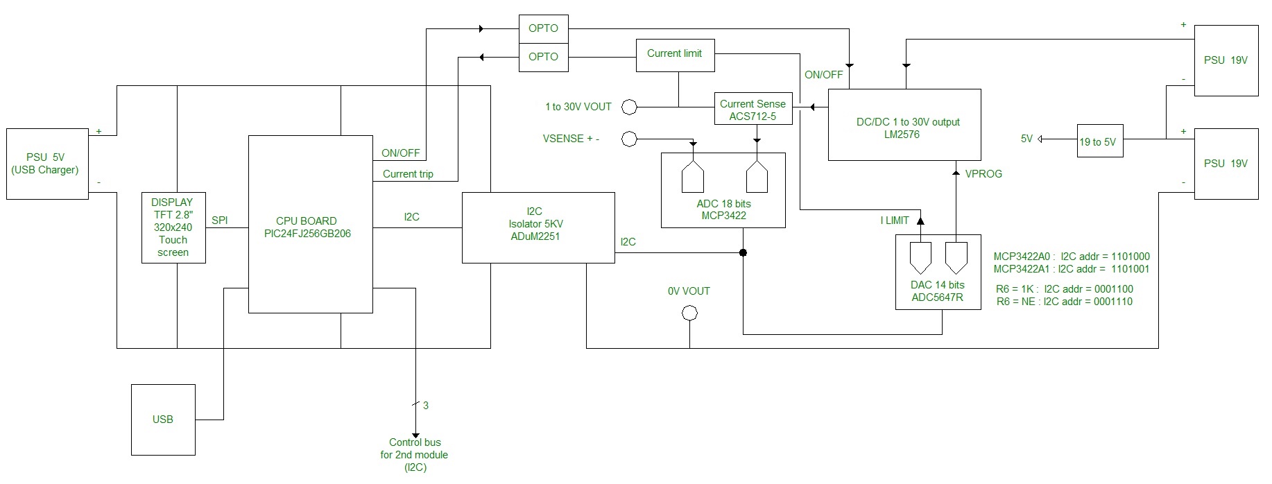
The FCALLBOX 2x30V 3A USB power supply described in this article is a new version (archive at the end of the article). It is more acurate and has a MCU more powerfull allowing a display more fluide The characteristics ar following : - Two programmable outputs 1 to 30V 3A max, isolated: Precision for the voltage : 1.4% max between 1 to 30V and 0.4% between 3 to 30V for a 0 to 3A load. Precision for the output current read : +/-2% max from 300mA to 3A and +/-5% max from 0 to 3A - Two fixed outputs 5V 3A max (0V coupled with each 1V of 30V output. - Possibility to set in serie the 30V outputs (2 to 60V 3A) or in symetrical mode (1 to +30V 3A and -1V to -30V 3A) - Possibility to set in serie the 5V outputs (10V 3A) or in symetrical mode (+5V and -5V 3A) - One fixed output 5V 3A (0V coupled at the output 1 of 1 to 30V). - Current limit programmable from 0 to 3A, software and hardware. - Display and command with a TFT 2.8" with tactil touch. - programmable by USB, with port isolated to the outputs (the 0V is not connected to the 0V of your USB port of your PC.) SommaireBlock diagramThe PSU includes : - Four PSU blocks 230V to 19V 30W. - Two PSU boards with CPU. - A TFT 2.8" display with tactil touch. - Two outputs 1 to 30V isolated. - Two outputs 5V 3A isolated, but their 0V is coupled to the 0V of each 30V output. Below the block diagram of one of two blocks :
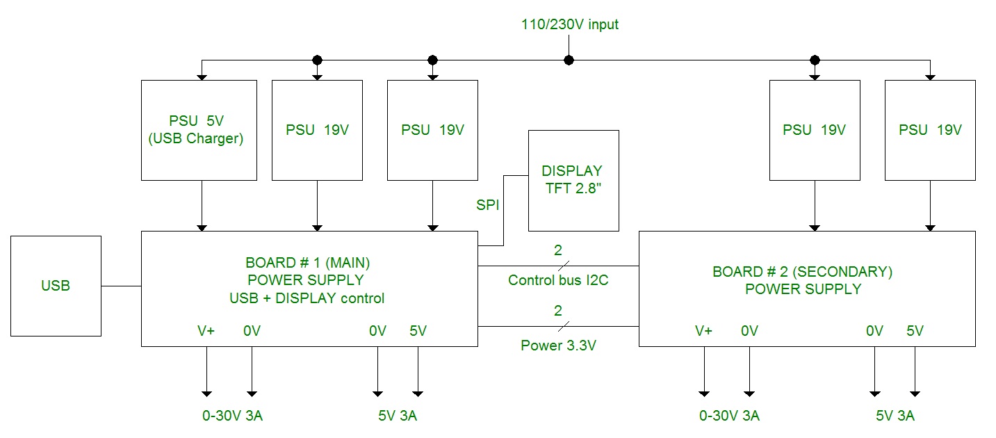
Download the block diagram here Then the block diagram of the Power supply :
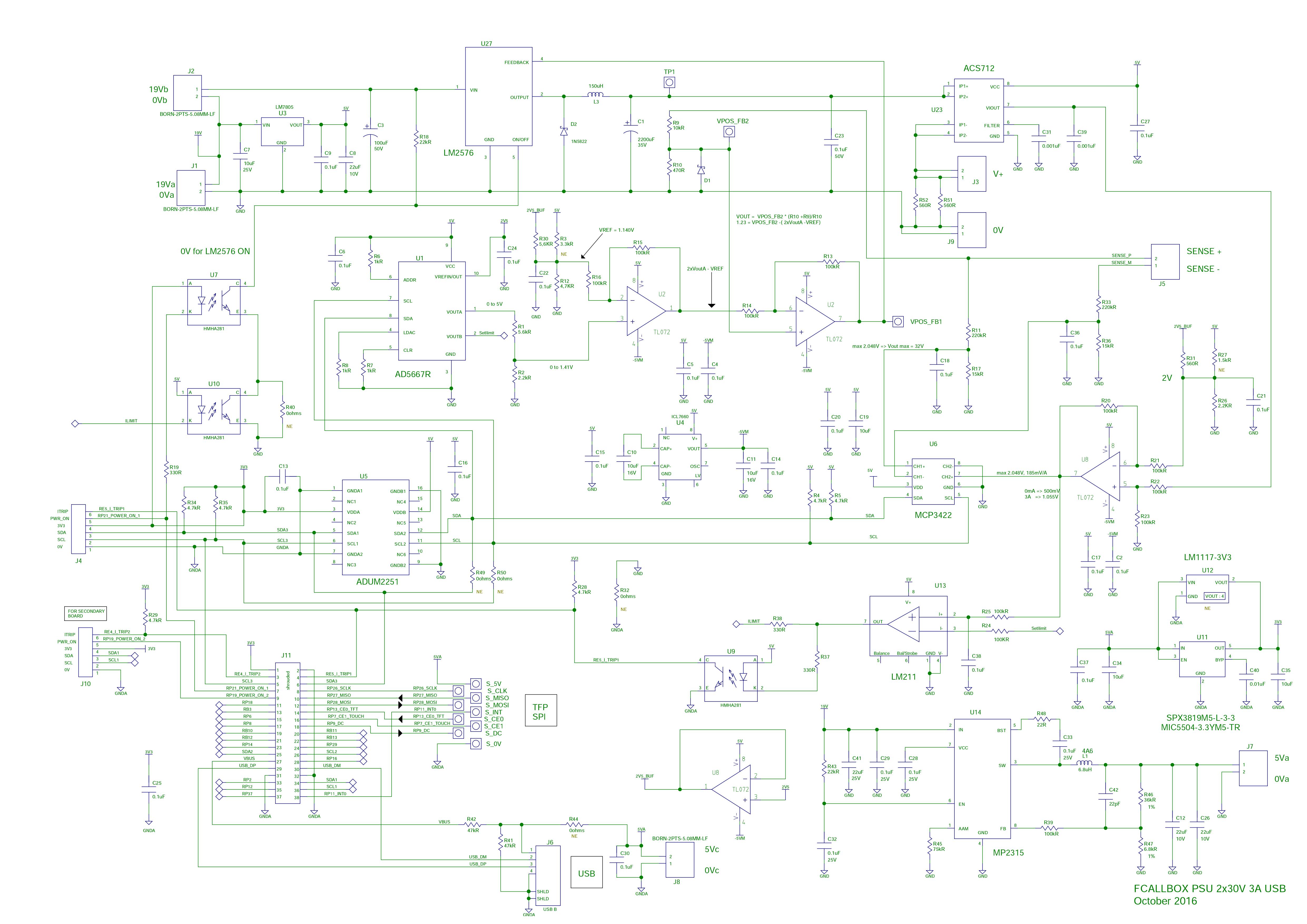
Download the block diagram here SchematicThe schematic of the board :
Download the schematic here Some explainations : - The power supply analog part is based on a switching regulator LM2576 U27. - The output voltage control is done by inserting an AOP U2 in the feedback loop, this one is controled by a DAC 14bits AD5667R U1 with an integrated stable reference voltage.Note : the feedback is taken on SENSE + which must be wired to the the socket V+ on the front panel - The output current measurement use a "current sense 5A" ACS712 U23, its output (185mV/A) is amplified by U8 and connected to a ADC 18bits MPC3422 U6. - The ADC and the DAC are set in I2C by the 18F4550 U9. The bus is isolated by ADUM2251 U5 to electricaly separate the USB port from the voltage outputs. - The LM2576 ON/OFF control pin is controled by the CPU and isolated with HMHA281 U6. - The IC ICL7660 U4 is used to generate -5V for the AOP to allow their output under 0V to get LM2576 output at 1V - To allow a quick current limit protection, it has been added a comparator LM211 U13 on the current sensor output, the threshold is set by the second output of the DAC U1. - The 5V 3A is done with MP2315 U10. Bill of materialThe BOM below shows only the components to populated.For the board #2 (SECONDARY), the components on the red cells must not be mounted,
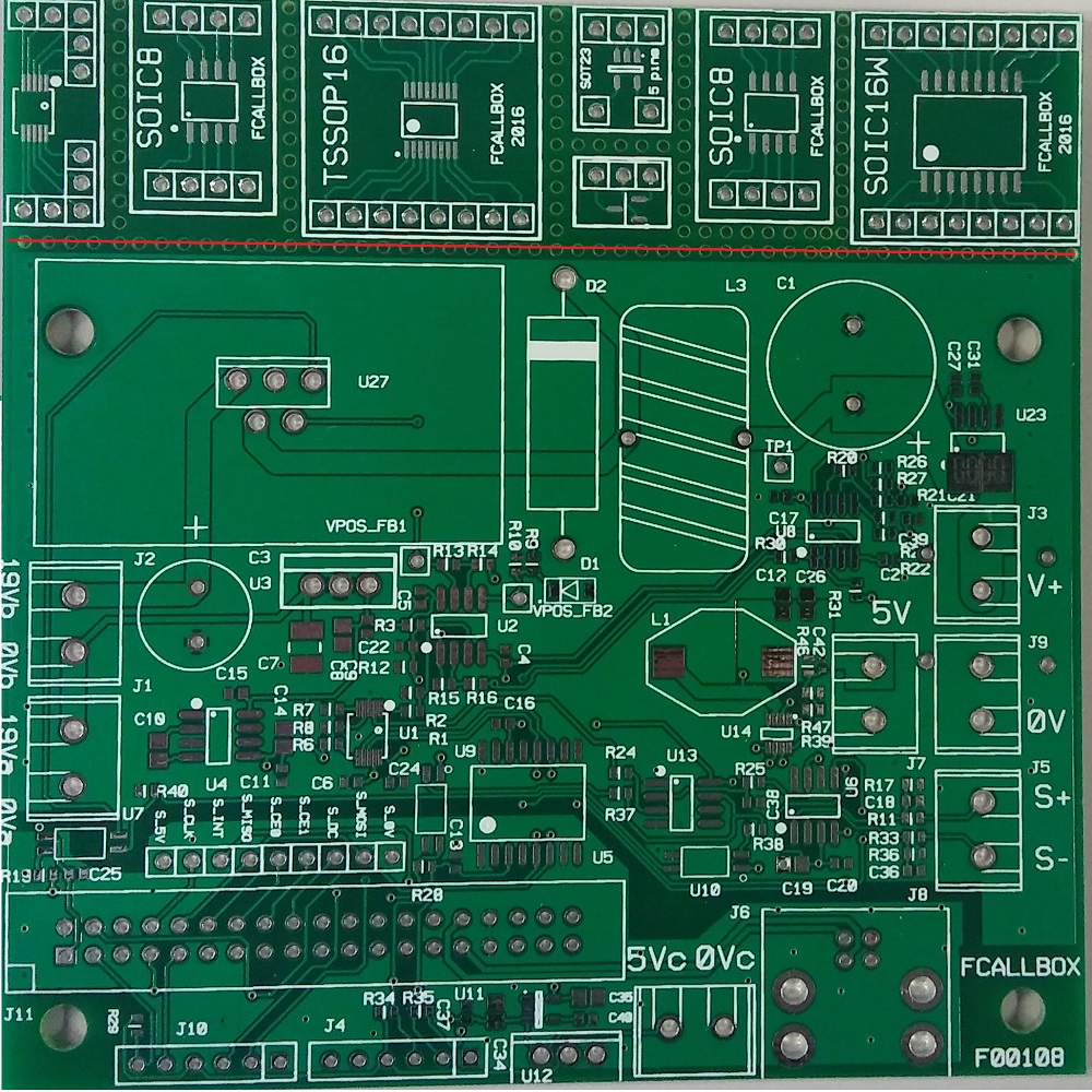
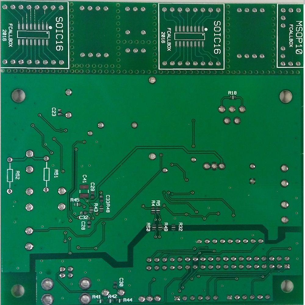
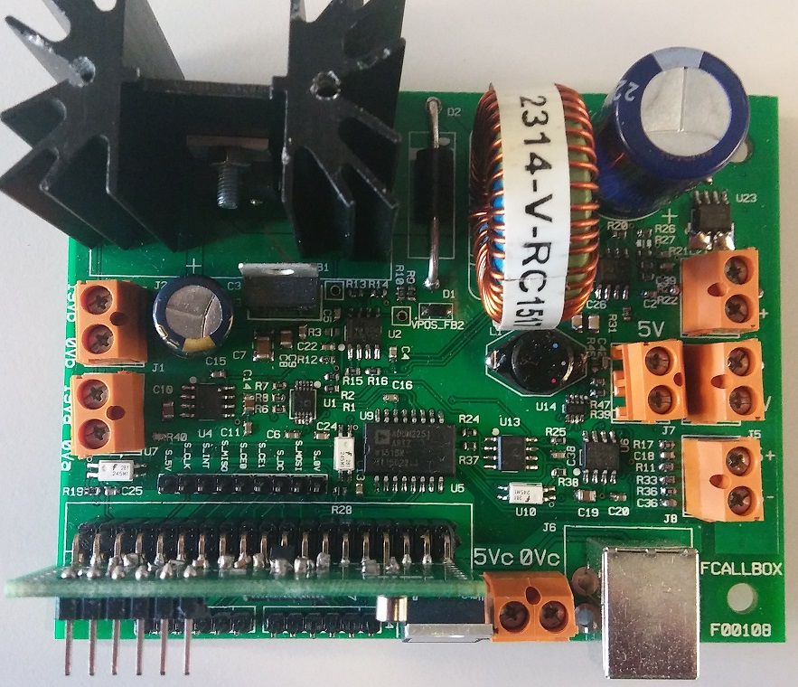
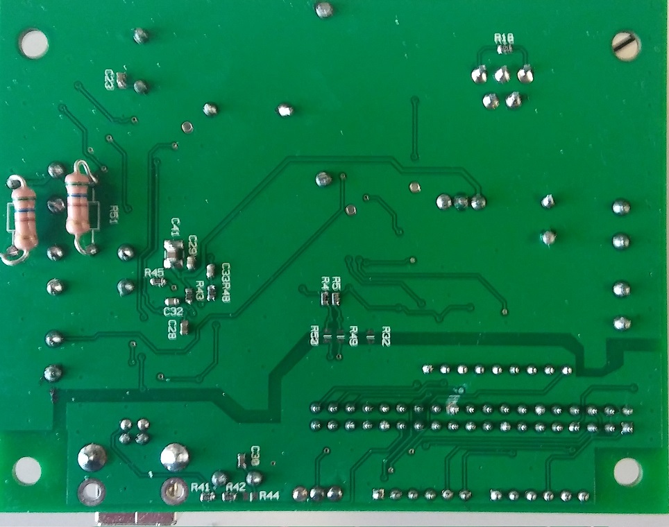
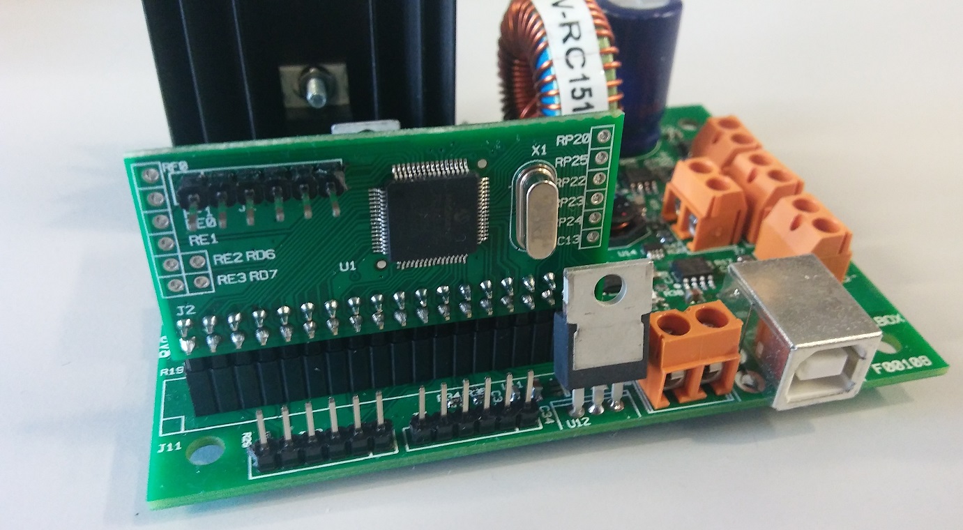
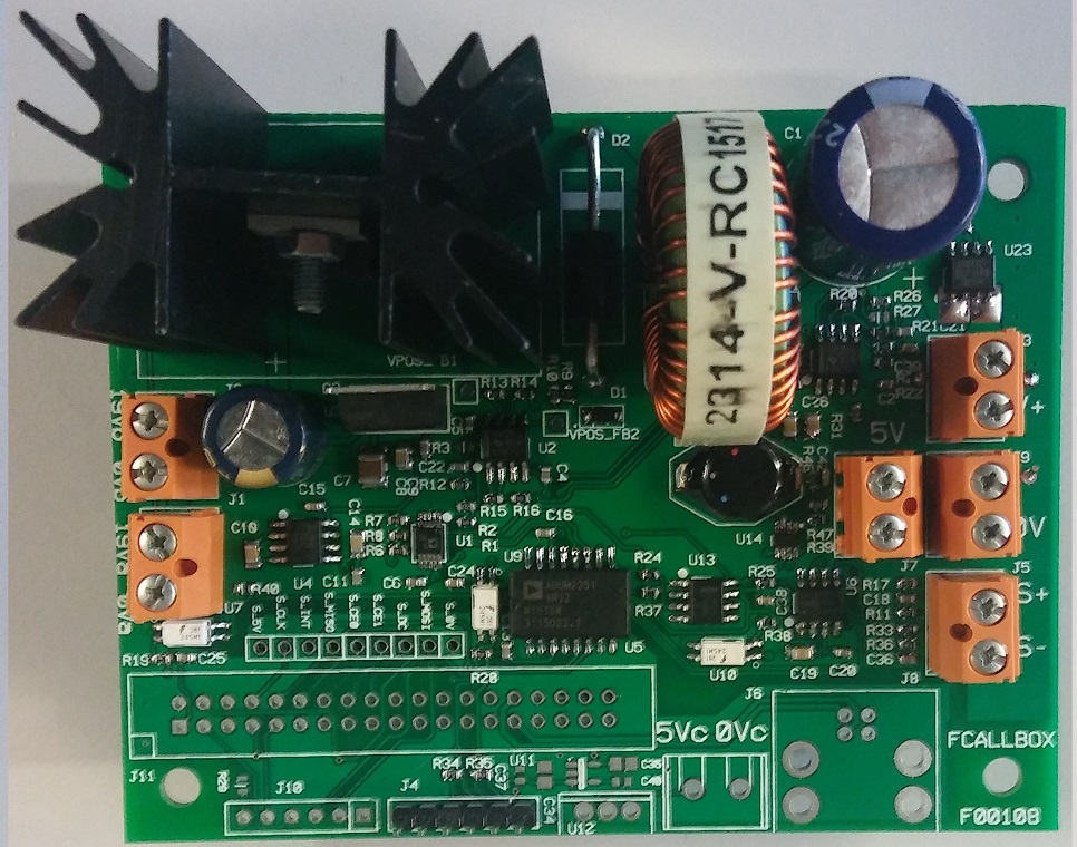
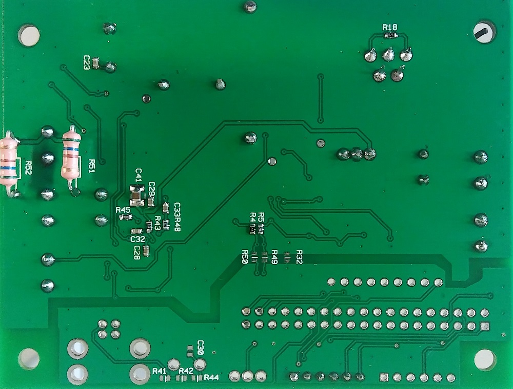
PCBThe board dimensions are 100x75mm, as the PCB prototype standard dimensions are 100x100mm, I have added some adaptors SMD to DIL on the unused surface. So you have to cut the PCB on the red line. Below the picture of the PCB F00108
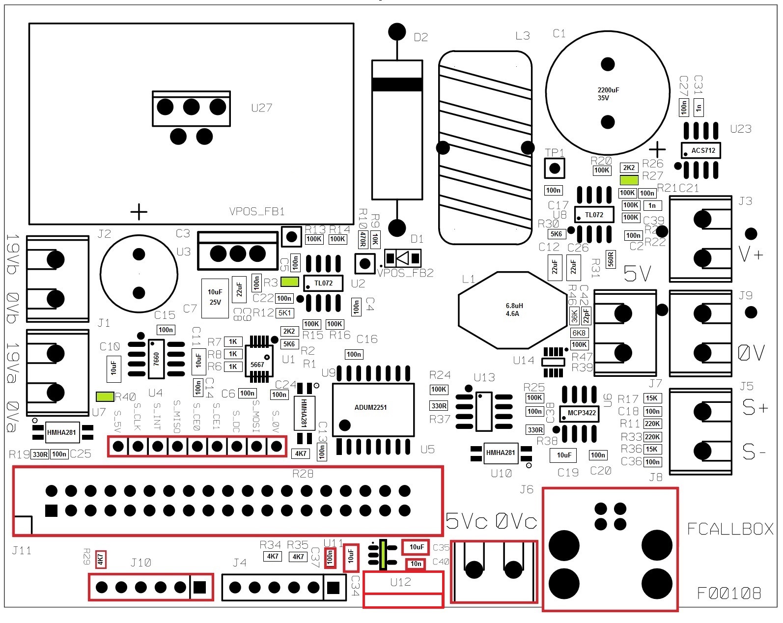
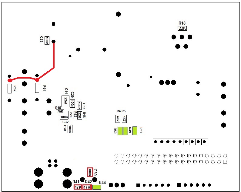
AssemblyThe board has components on the two faces. The parts in green must not be soldered. The parts in red must not be soldered for the secondary board. R56 and R57 must be wired as described in the drawing (not like the pictures), this improves the current measurements.
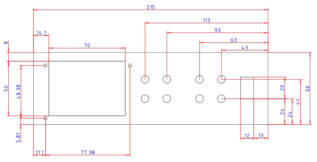
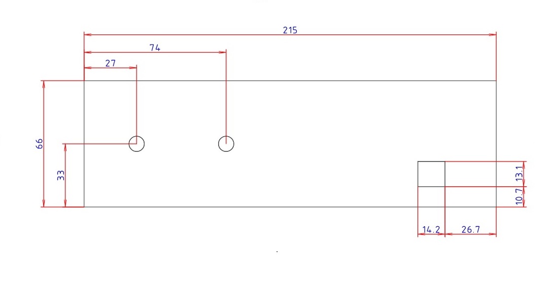
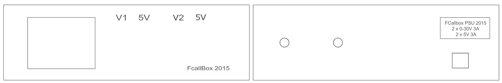
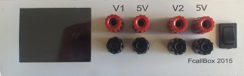
MechanicalThe PSU described here uses a box Bopla 55520010.MT, but you can adapt any kind of enclosure. FRONT AND REAR PLATE PROPOSAL
Download here the front plate drilling drawing in pdf
Download here the rear plate drilling drawing in pdf
Download here the silkscreen drawings in pdf
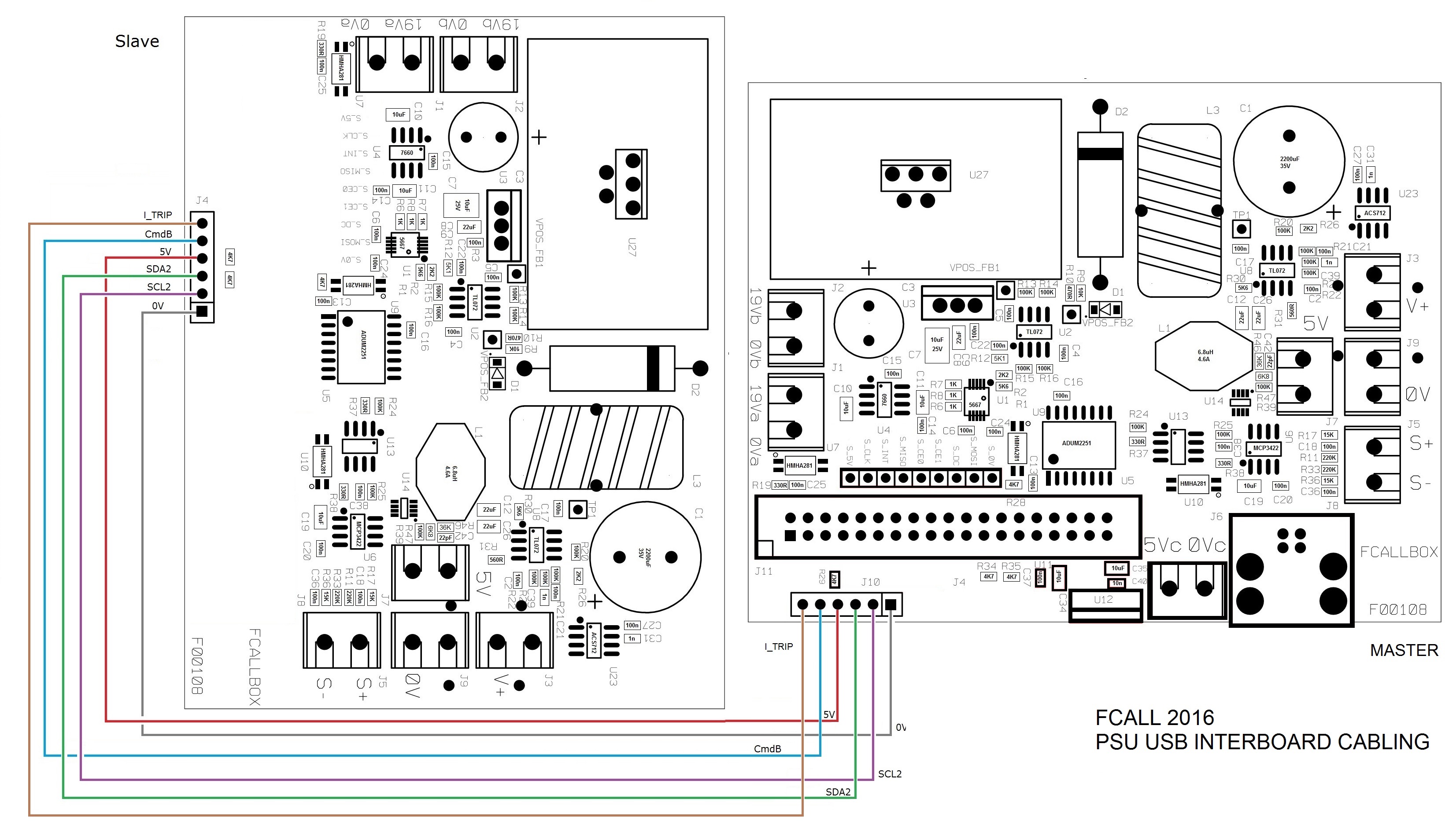
CablingINTERBOARD CABLING This is the connections between the master and slave boards
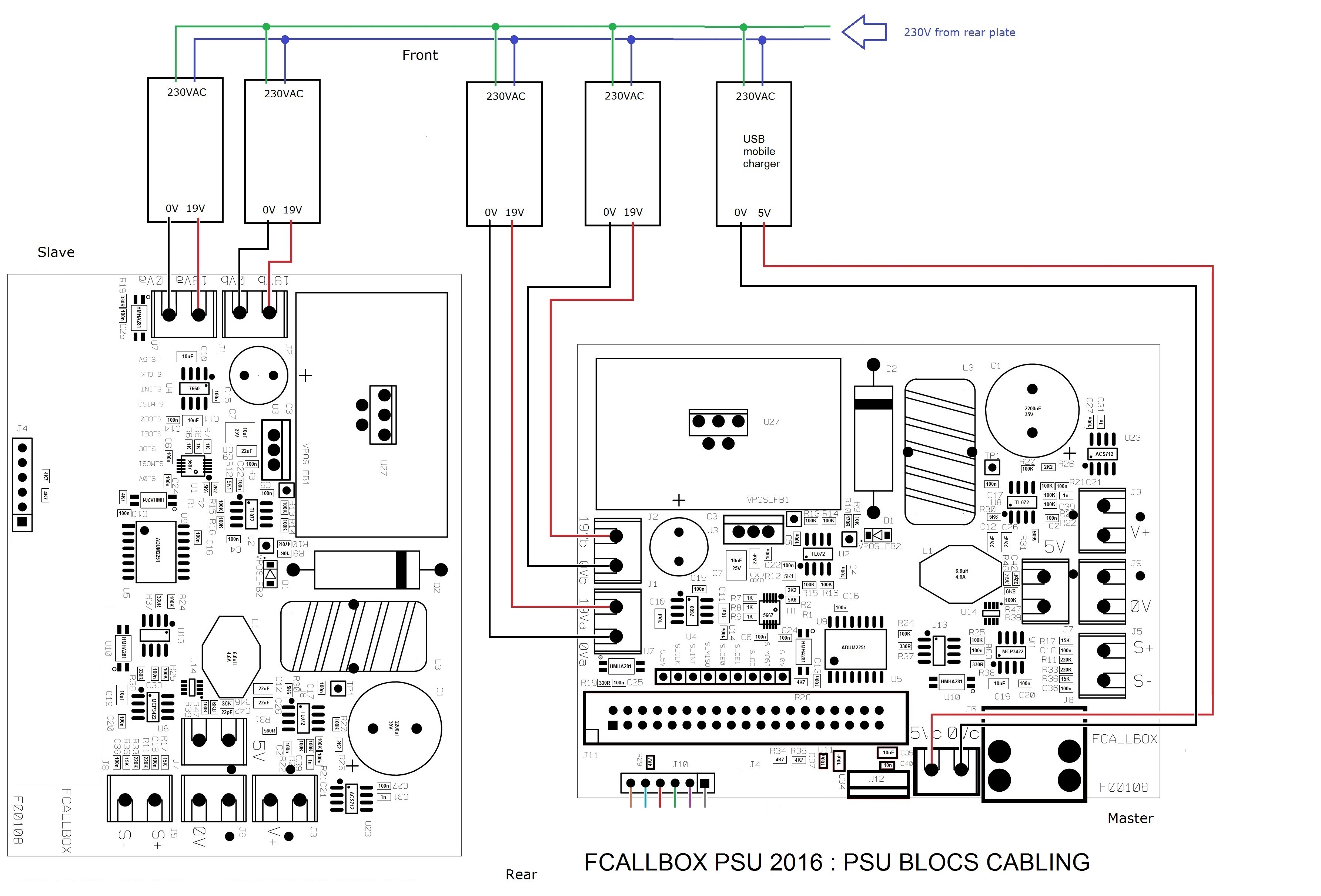
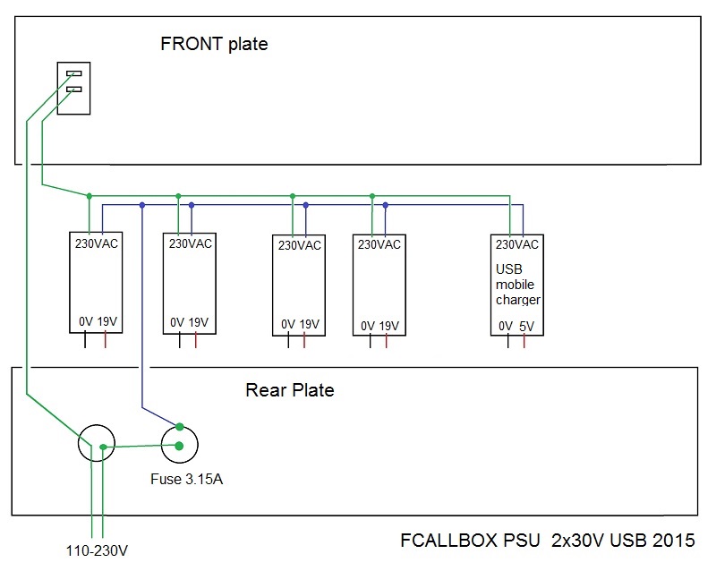
PSU MODULES CABLING The primary inputs 110/230V of the 4 blocs are wired in parallel and will be connected to the rear panel. Each output 0 and 19V of each bloc is connected to the 0Va 19Va 0Vb 19Vb inputs of the boards, use AWG16 wires or less (bigger diameter).
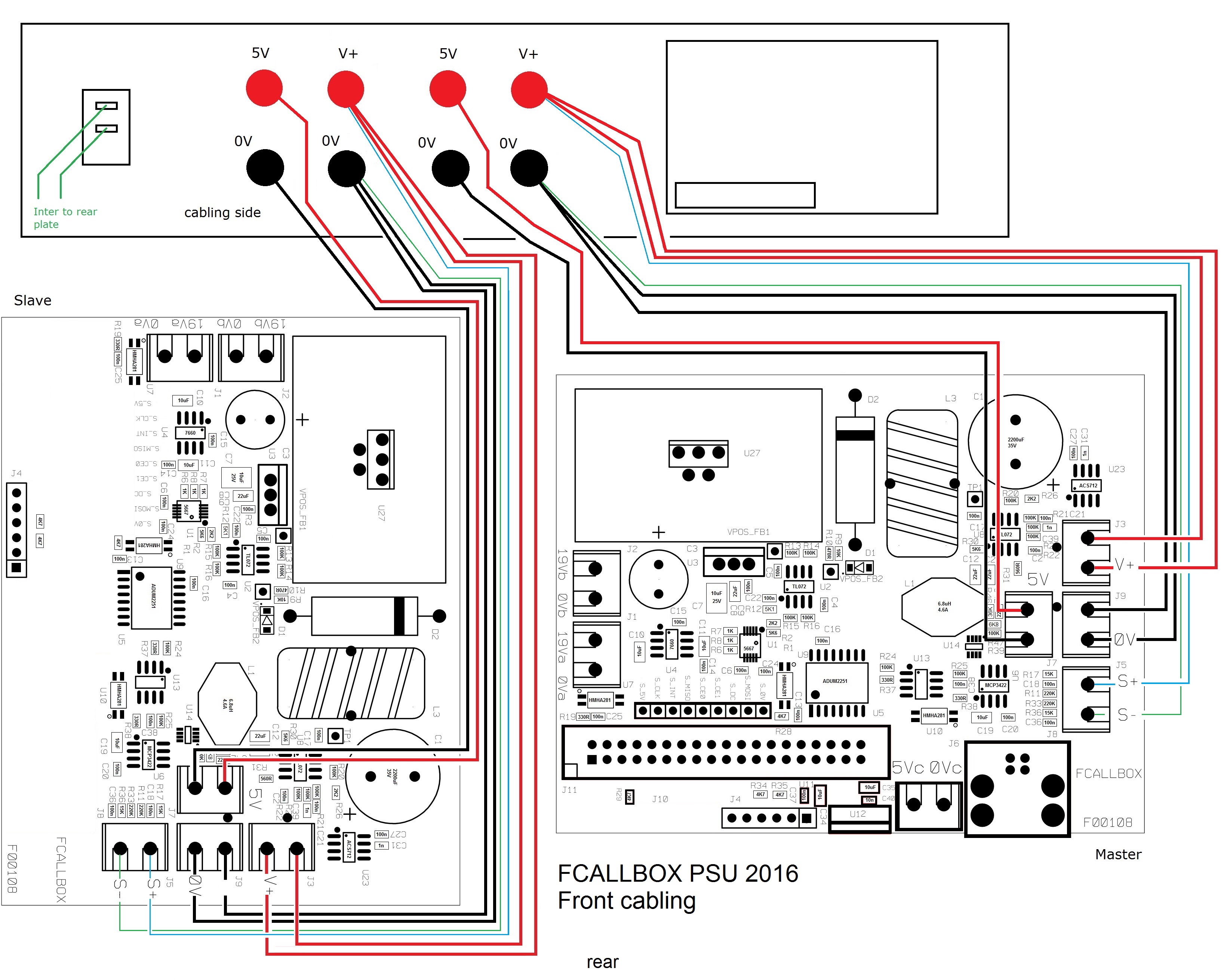
FRONT FACE CABLING To avoid important voltage drop under the cables, use AWG16 wires or less (bigger diameter)
FRONT REAR CABLING
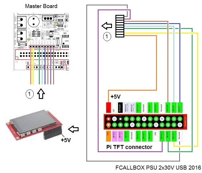
DISPLAY CABLING
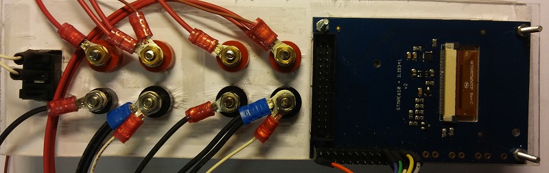
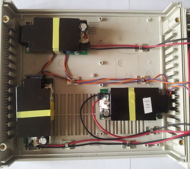
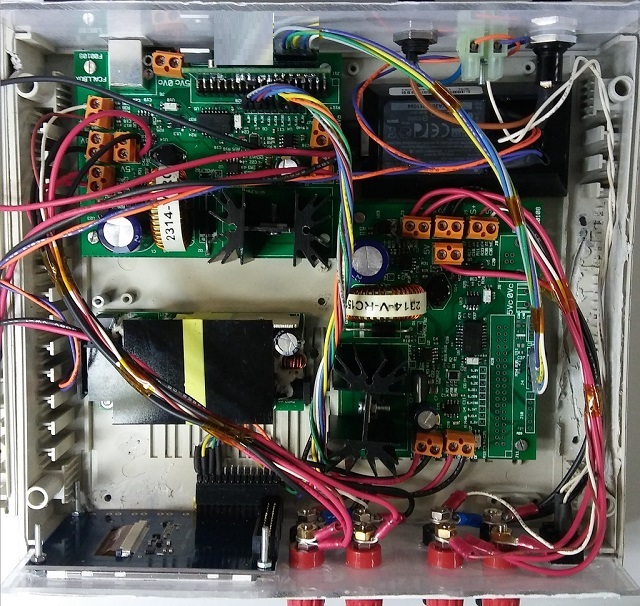
CABLING PICTURES PSU blocs cabling
Main cabling
PIC programmationDownload here the zip of th file HEX V2.15 to program the PICPickit2 connection The programmation can be done with a pickit3 or a ICD3, below the correspondance for the pin 1 of the programmer 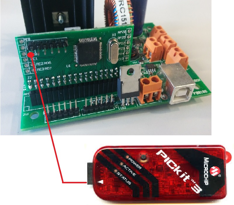
If everything is ok, you should see the boot screen below : 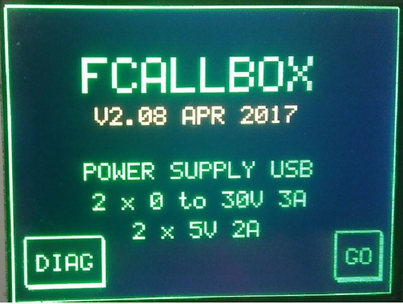
Press on the display to go to the main menu (It will go automaticaly after 30s if no user action) 
The T in yellow means traking ON, if red, OFF The checkbox ON/OFF indicates the output state : In red : output OFF, in green : output ON Press the chekbox to change the output state On OFF state, you see the output voltage set, and the current limit: 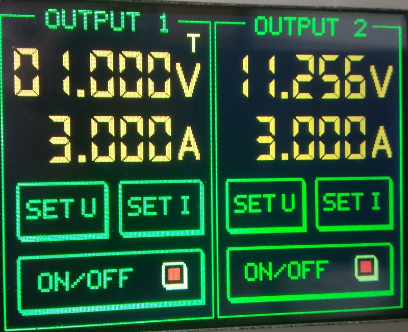
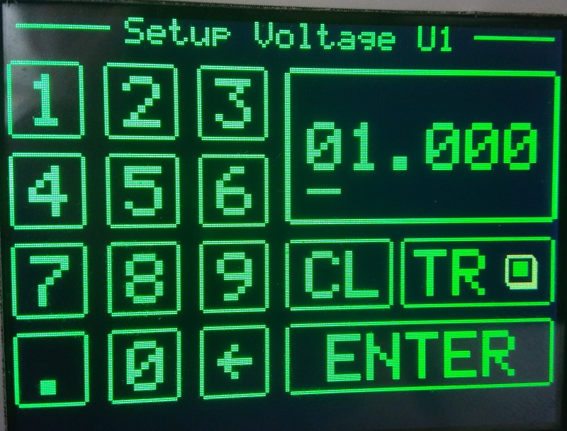
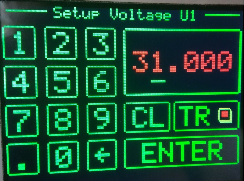
To set the output , press SET U: You have then access to a keyboard Press CL set the voltage to 00.000V Press TR to set tracking ON or OFF Press ENTER, set the value, and comes back to the main menu, except if the voltage is not on the range 1V to 30V. In this case tha value is displayed in red and you must entry a new value.
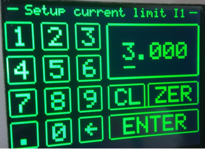
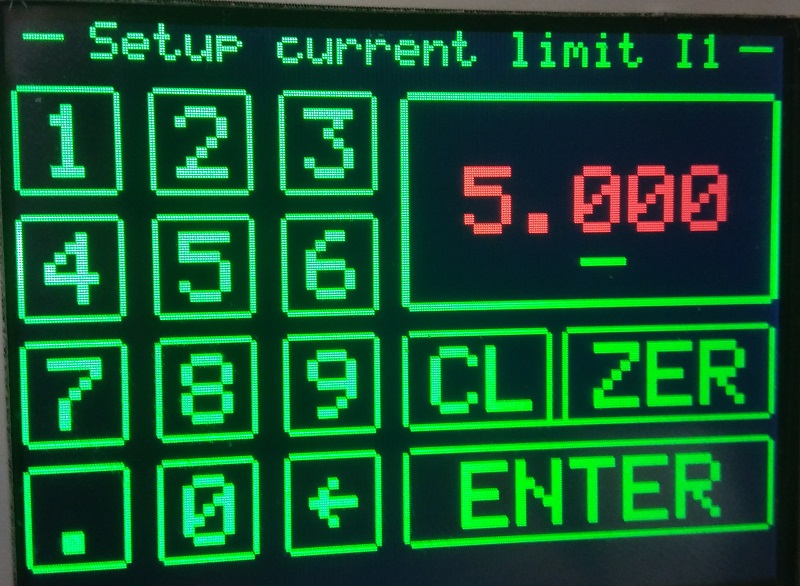
To set the current limit, press SET I: Press CL set the current to 0.000A Press ZERO to calibrate the current to 0 Press ENTER, set the value, and comes back to the main menu, except if the current is not on the range 0 to 3A.
Note : when the current limit triggers (less than one second), the PSU goes in OFF mode You have then to fix the default, before restart with ON/OFF button As the current measurement varies with the temperature, when the current becomes negative, the current display is : 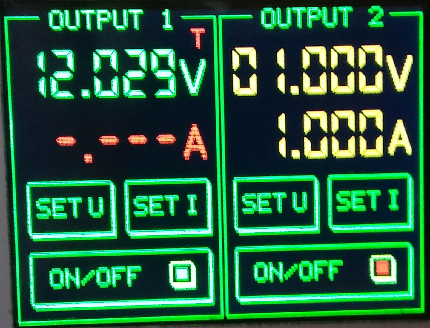
A zero setting is needed by using SET I then ZER Windows software to remote control the PSU through USBThe remote software allows to control the PSU through USB. But it is also neccessary to calibrate the PSU. Download here the file and unzip it in a folder then launch FcallBoxPSUremoteV121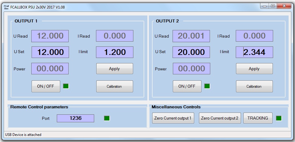
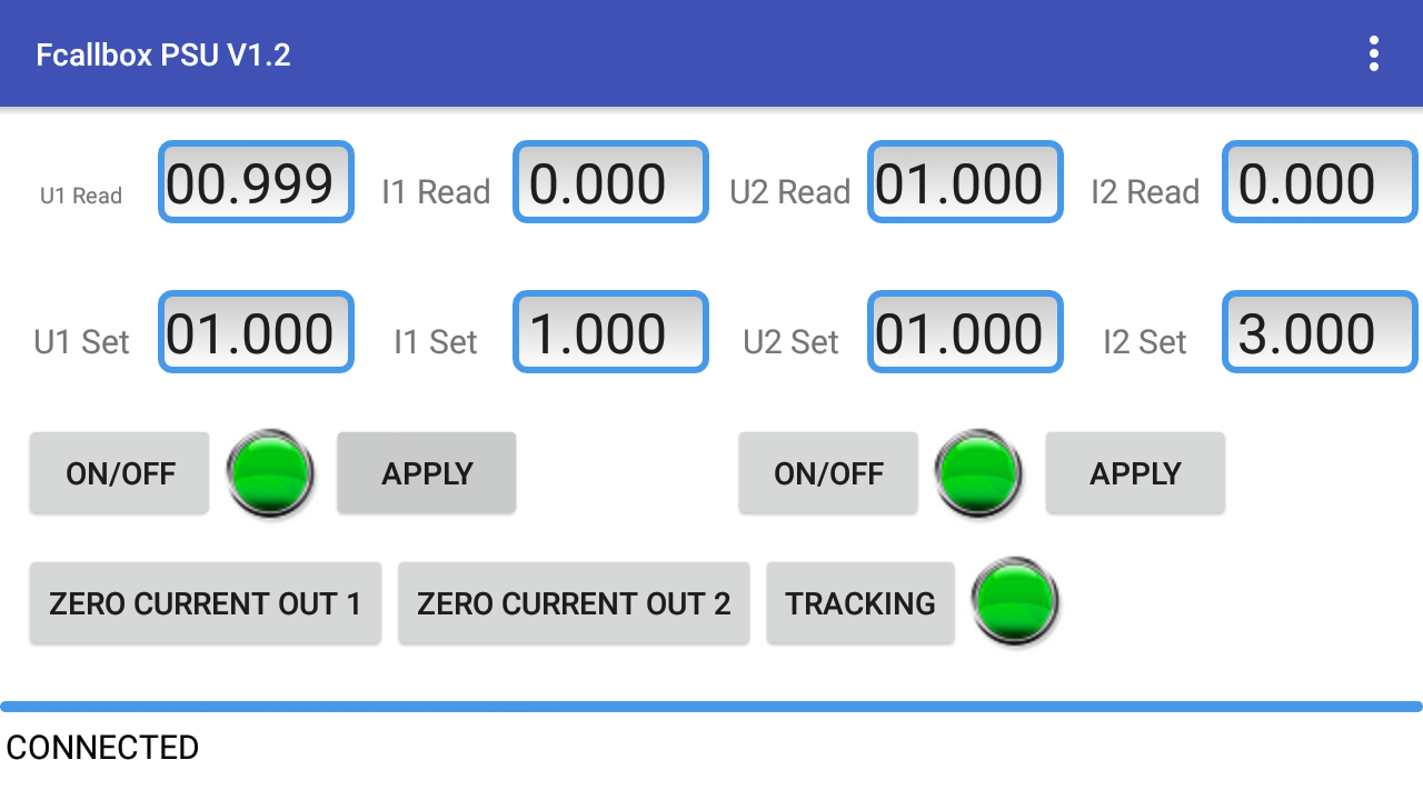
For each output : - Uread indicates the voltage read. - Iread indicates the current read. - USet the output voltage set, it is editable, press ENTER or Apply button to apply. - ISet same thing but for the current limit. - Power indicates the power consumed by the load on the output. - ON/OFF in red output OFF, in green for ON, press the button to change the state.- In the window Miscellaneous Controls : - The buttons Zero Current output 1 an Zero Current output 2 allow to reset the current read. - The tracking button set the PSU in a mode where the output voltage is adjusted to the voltage read, this allows to compensate the voltage drop due to high load .When OFF, Uread and Iread display nothing, but you can set the current and voltage : 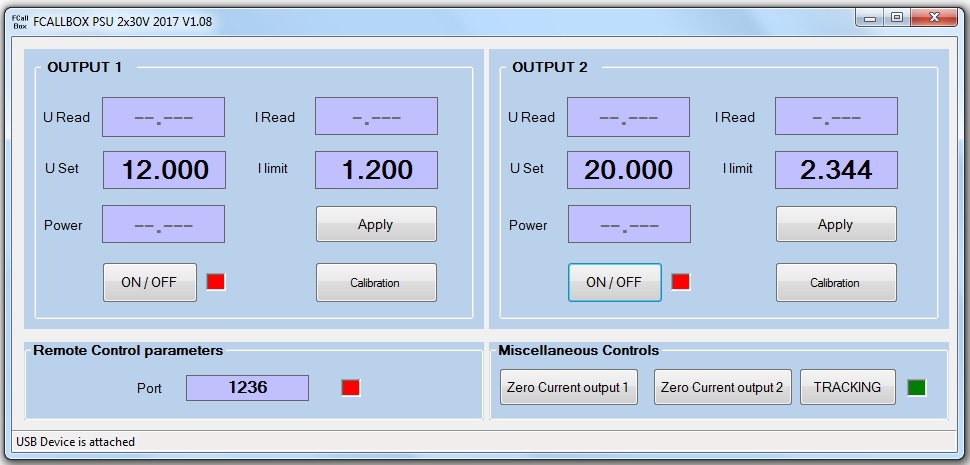
When OFF, Uread and Iread display nothing, but you can set the current and voltage :
As the current measurement varies with the temperature, when the current becomes negative, the current display is in red and the button Zero Current Output blinks, meaning that a Zero calibration is needed : 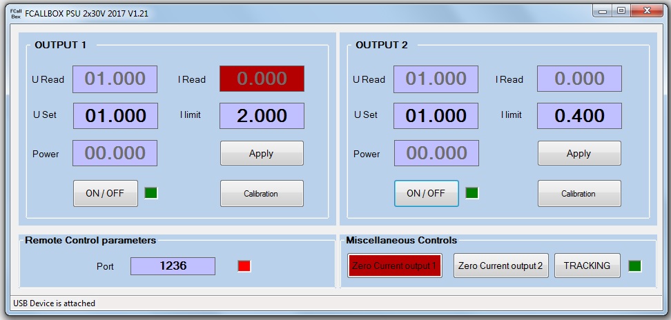
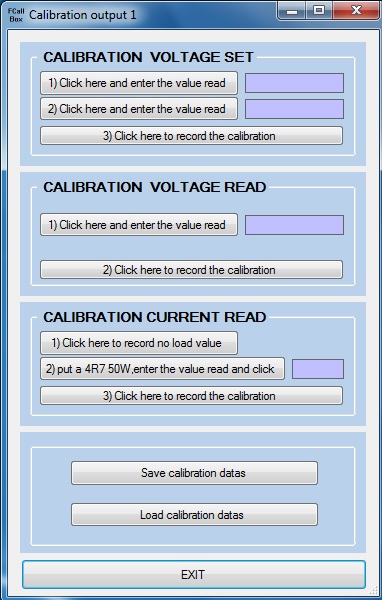
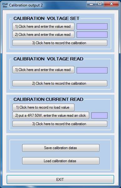
The calibration is done with the remote software through USB :
Each opération can be done individually. Calibration of the output voltage (CALIBRATION VOLTAGE SET): - Click on button 1, wait for thee voltage stabilized, measure the output voltage with a multimeter, write the value on the box at right. - Click on button 2, wait .., measure the output voltage with a multimeter, write the value on the box at right. - Click on button3, to compute and record the calibrations values on the PSU.Calibration of the output voltage read (CALIBRATION VOLTAGE READ): - Click on button 1, wait for thee voltage stabilized, measure the output voltage with a multimeter, write the value on the box at right. - Click on button 2, to compute and record the calibrations values on the PSU.Calibration of the current read (CALIBRATION CURRENT READ): - Click on button 1, this record the value when no load connected at the output (zero calibration). - Put a 4.7R 50W load on the output in serie with a amperemeter, get the current and write the value on the box at right then click on button 2. - Click on button 3, to compute and record the calibrations values on the PSU.Save or reload calibration datas : - For each output, it is possible to save Save calibration datas or restore Load calibration datasLinux software to remote control the PSU through USBThe remote software allows to control the PSU through USB. Note that the calibration is not possible with the Linux version and must be done one time on Windows. The software has been writen in python, you have to execute the installations following in root mode : - sudo apt-get install python-pygame - apt-get install python-pip - pip install pyusb Download here the file and unzip it in a folder then launch python ps.pyDisplay when PSU is not powered ON or not connected through USB 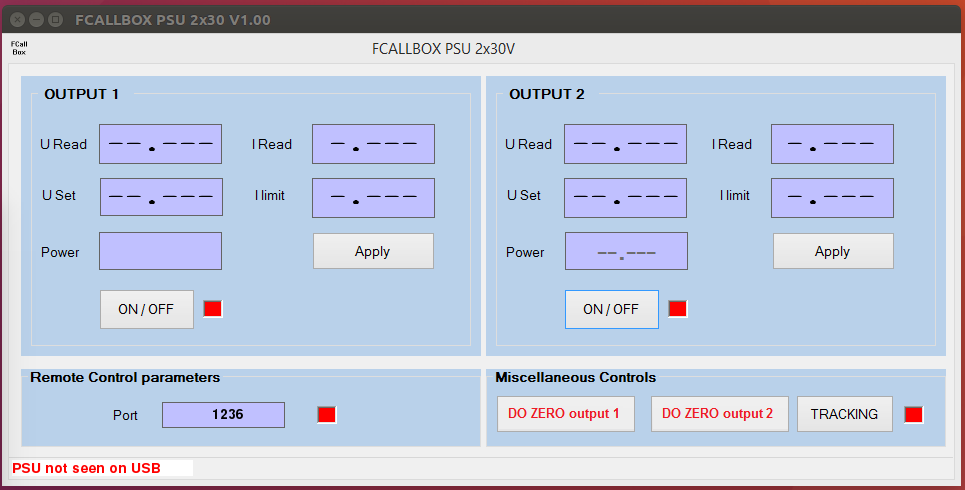
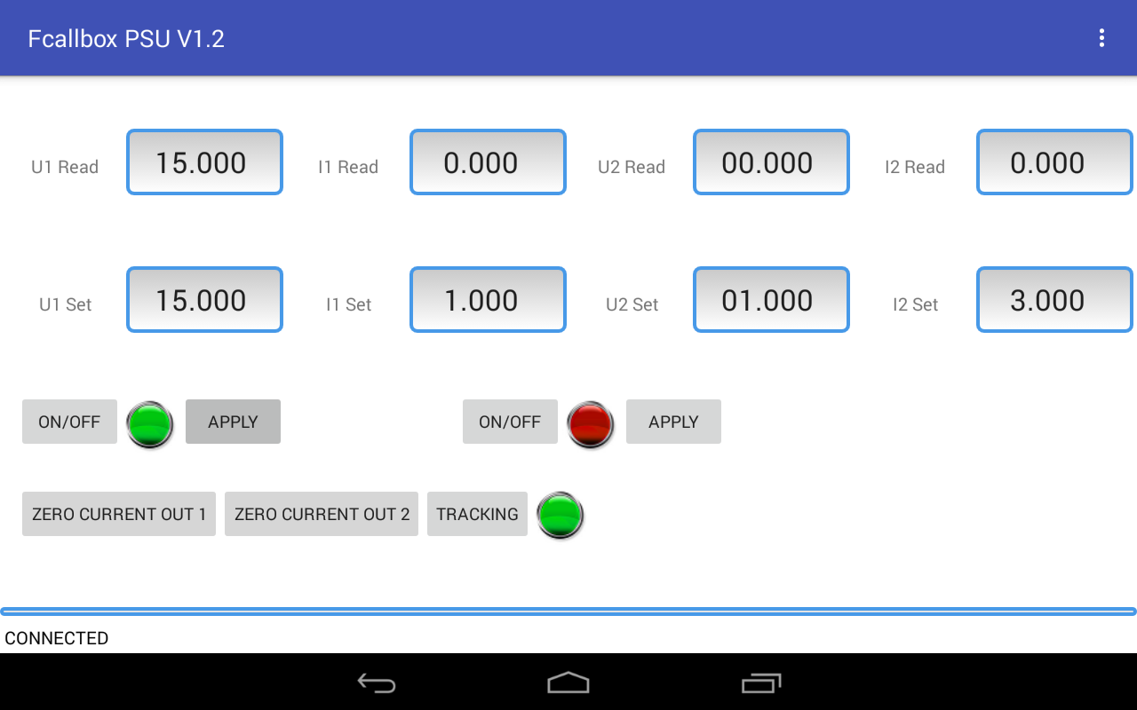
Display when PSU connected 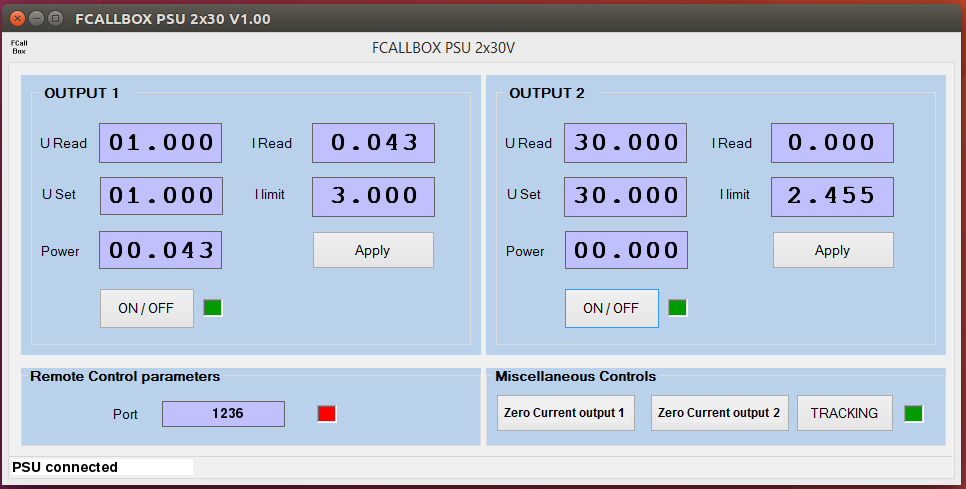
As the current measurement varies with the temperature, when the current becomes negative, the current display is : 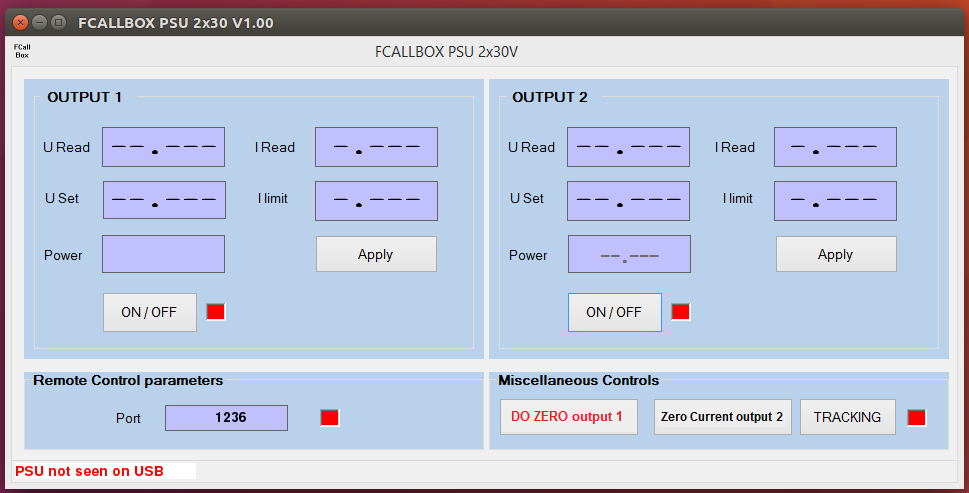
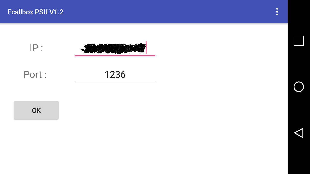
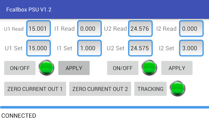
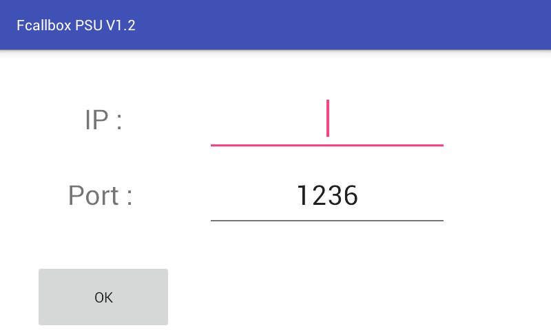
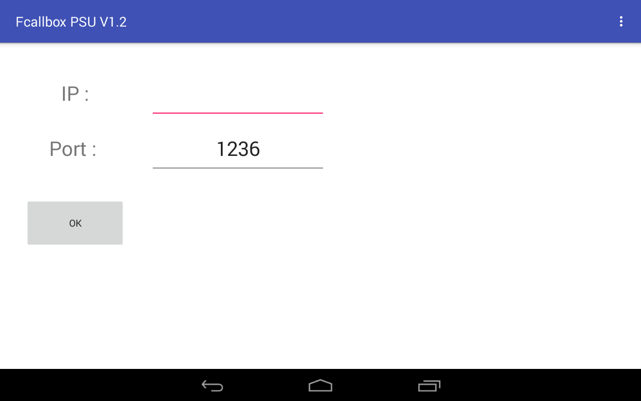
A zero setting is needed by clicking on DO ZERO OUTPUT Software under Windows or LINUX : remote controlThe application can be remote controled throug a link Socket Server-Client in UDP The field IP and Port must be configured, use 127.0.0.1 if the remote control software is on the same PC The available commands are listed below : The command must be followed by \n The read commands below return the command followed by the value and \n for eg : READ_U1_VOLTAGE12.123\n READ_U1_VOLTAGE : return voltage read on Output #1READ_U2_VOLTAGE : return voltage read on Output #2 READ_U1_SET : return voltage set on Output #1 READ_U2_SET : return voltage set on Output #2 READ_I1_CURRENT : return current read on Output #1 READ_I2_CURRENT : return current read on Output #2 READ_I1_LIMIT : return limit current on Output #1 READ_I2_LIMIT : return limit current on Output #2 READ_U1_STATE : return state for Output #1, equal to 1 if ON READ_U2_STATE : return state for Output #2, equal to 1 if ON READ_TRACKING_STATE : return tracking, equal to 1 if ON The write commands below return OK + \n for eg : OK\n SET_U1_VOLTAGE : set voltage for Output #1, return OKSET_U2_VOLTAGE : set voltage for Output #2, return OK SET_I1_LIMIT : set current limit for Output #1, return OK SET_I2_LIMIT : set current limit for Output #2, return OK SET_U1_ON : set Output #1 ON, return OK SET_U2_ON : set Output #2 ON, return OK SET_U1_OFF : set Output #1 OFF, return OK SET_U2_OFF : set Output #2 OFF, return OK SET_CURRENT_LIMIT_ON : set current limit ON for Output #1 and #2, return OK SET_CURRENT_LIMIT_OFF : set current limit OFF for Output #1 and #2, return OK SET_VOLTAGE_TRACKING_ON : set voltage tracking for Output #1 and #2 (software try to adjust the voltage output to fit the voltage read and set), return OK SET_VOLTAGE_TRACKING_OFF : disable voltage tracking for Output #1 and #2, return OK ZERO_1 : calibrate current read at 0 (compensate offset due to temperature change) for output #1, return OK after several second ZERO_2 : calibrate current read at 0 (compensate offset due to temperature change) for output #2, return OK after several second Android application to control the PSU through the Windows or Linux softwaresThe Android application allows the control remotely of the PSU sofware and so the PSU with a mobile or tablette under Android The application has the same capablilities of the Windows software except the calibration of the PSU. At the first launch, the setting screen is displayed, set the IP of the PC which runs the window or Linux software, also set the port which is 1236 in default.
As the current measurement varies with the temperature, when the current becomes negative, the current display is in red and the button Zero Current Output is in red, meaning that a Zero calibration is needed :
Qualifications and measurementsMeasurement Setup : 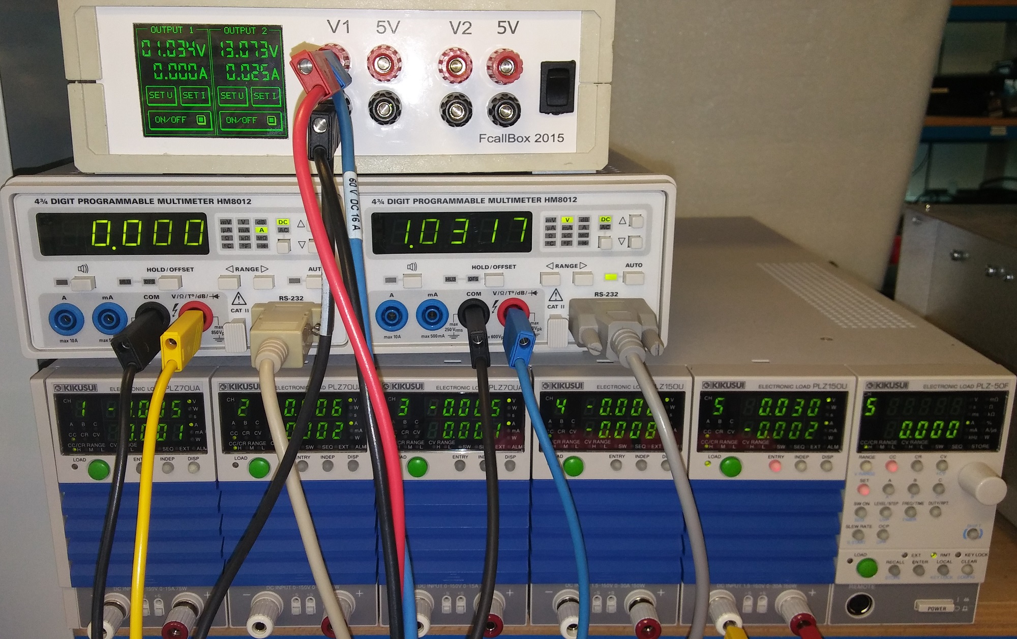
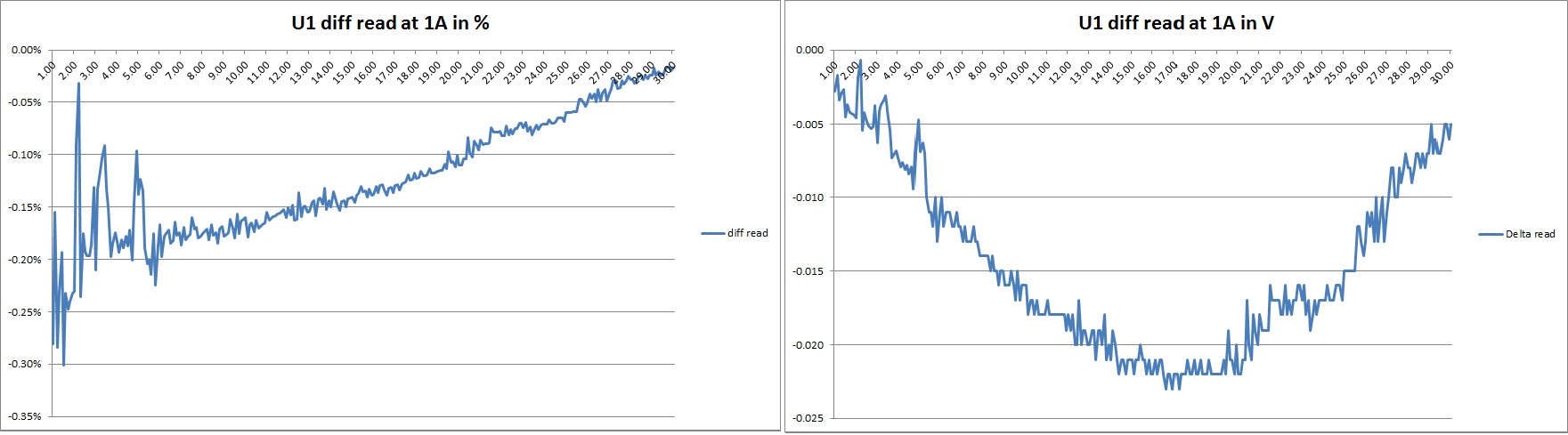
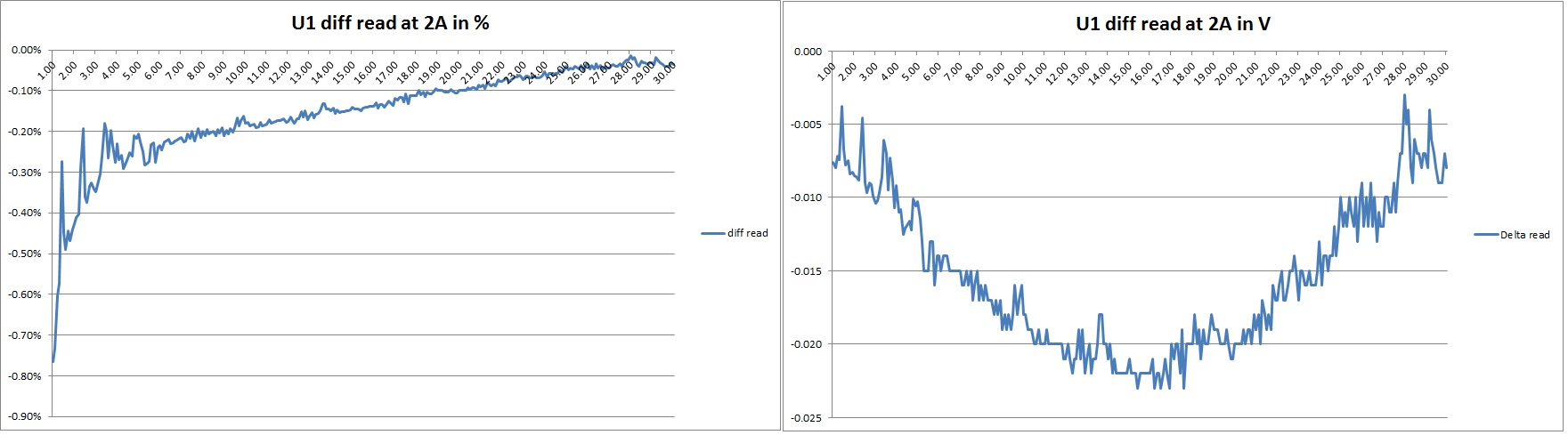
Check between 1V to 30V with no load then 1A, 2A and 2.9A : below the results for the differences between the voltage read by the PSU at the OUTPUT 1 compared with an external multimeter : - The precision max is 0.2% @ 0A , 0.3% @ 1A, 0.75% @ 2A, 1.3% @ 2.9A in the range 1 to 30V - The precision max is de 0.2% @ 0A , 0.2% @ 1A, 0.2% @ 2A, 0.3% @ 2.9A in the range 3 to 30V 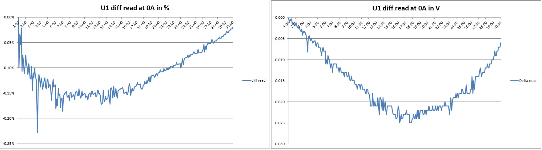

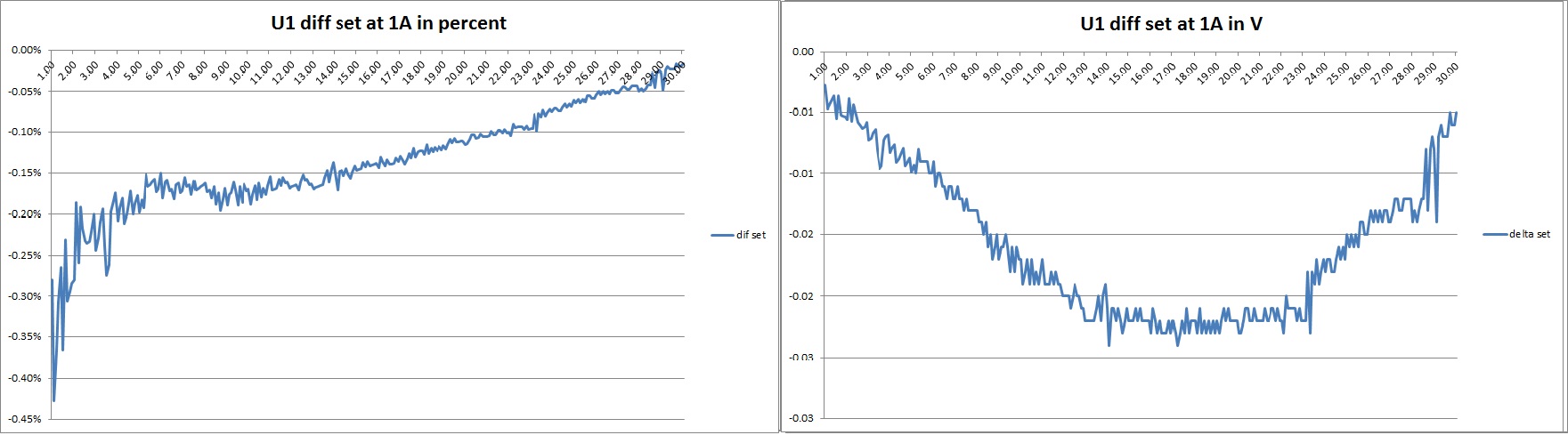
below the results for the differences between the voltage set at the PSU at the OUTPUT 1 compared with an external multimeter : - The precision max is 0.1% @ 0A , 0.4% @ 1A, 0.7% @ 2A, 1.4% @ 2.9A in the range 1 to 30V - The precision max is 0.1% @ 0A , 0.2% @ 1A, 0.3% @ 2A, 0.4% @ 2.9A in the range 3 to 30V 


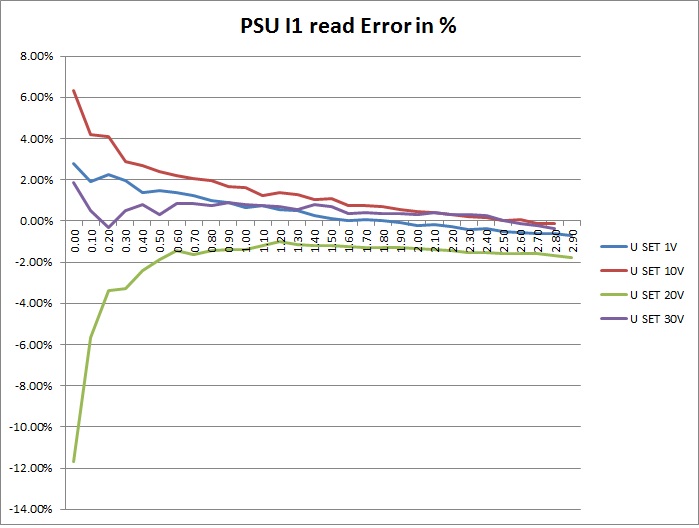
Check output current measured : below the results for the differences between the current read by the PSU on OUTPUT 1 compared with an external multimeter : - The precision max is +/-3% from 300mA to 3A and around +/-5% below 300mA 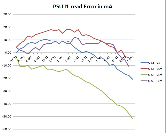
 Download here the measurement datas
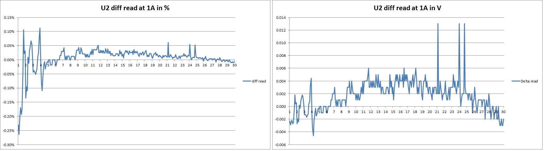
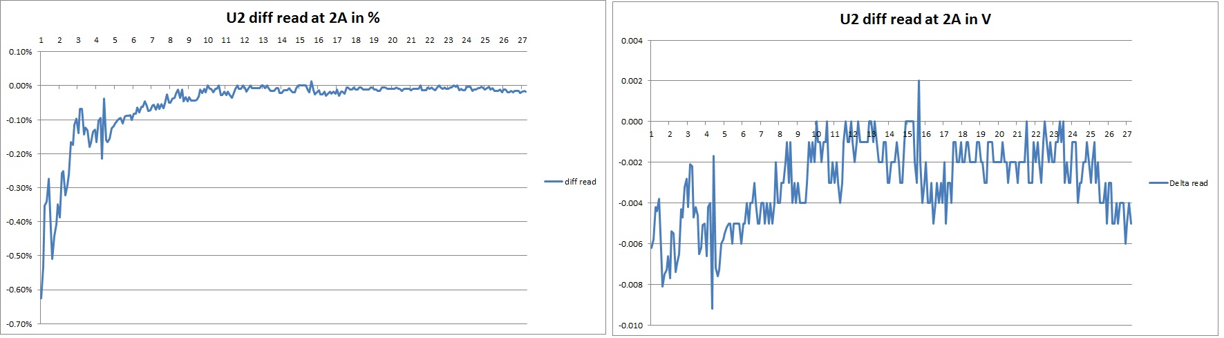
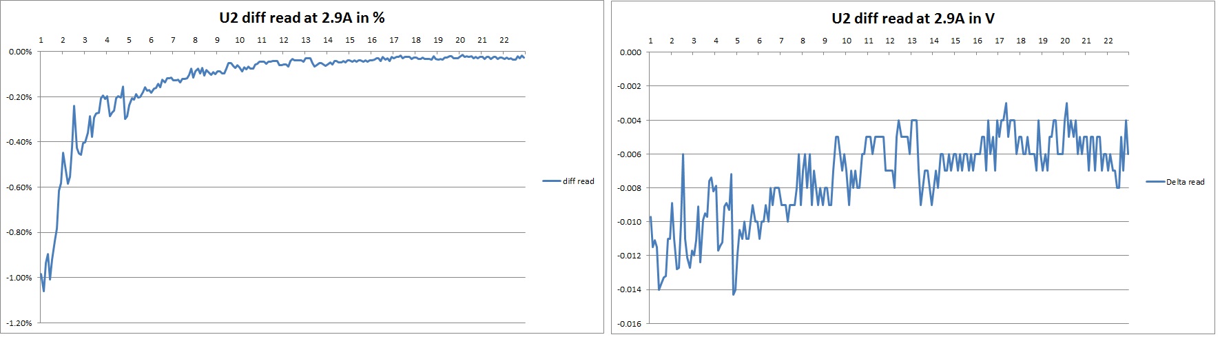
Check between 1V to 30V with no load then 1A, 2A and 2.9A : below the results for the differences between the voltage read by the PSU at the OUTPUT 2 compared with an external multimeter : - The precision max is 0.35% @ 0A , 0.3% @ 1A, 0.6% @ 2A, 1% @ 2.9A in the range 1 to 30V - The precision max is 0.2% @ 0A , 0.2% @ 1A, 0.1% @ 2A, 0.2% @ 2.9A in the range 3 to 30V 
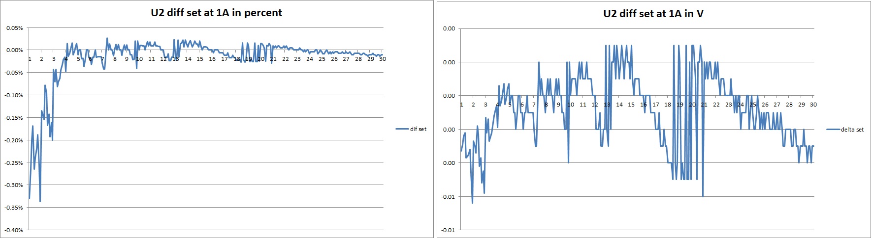
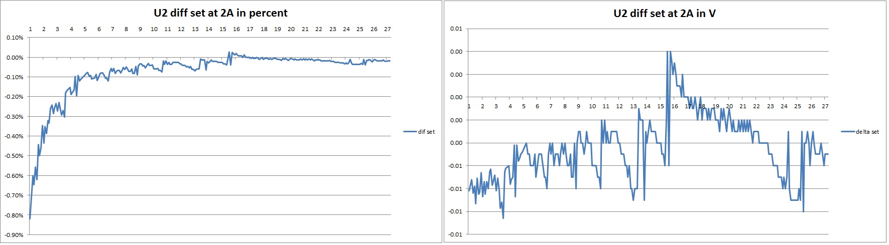
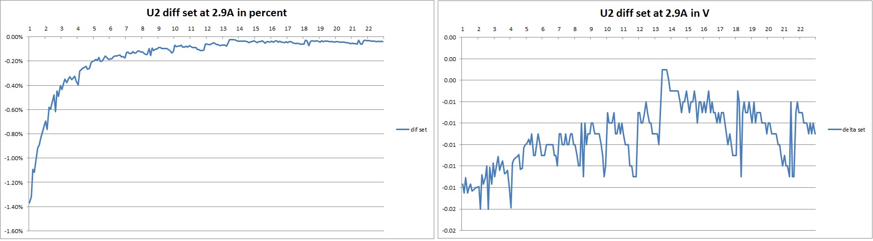
below the results for the differences between the voltage set at the PSU at the OUTPUT 2 compared with an external multimeter : - The precision max is 0.2% @ 0A , 0.3% @ 1A, 0.8% @ 2A, 1.3% @ 2.9A in the range 1 to 30V - The precision max is 0.1% @ 0A , 0.05% @ 1A, 0.3% @ 2A, 0.4% @ 2.9A in the range 3 to 30V 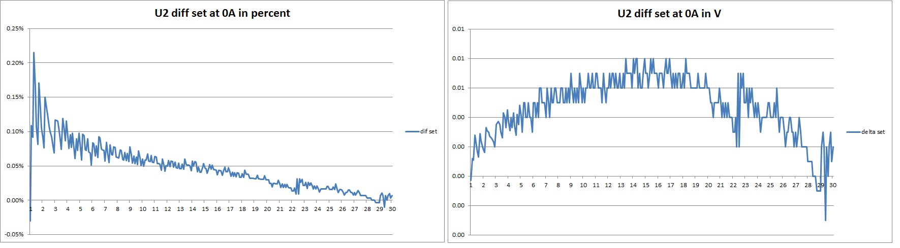
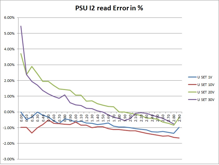
Check output current measured : below the results for the differences between the current read by the PSU on OUTPUT 1 compared with an external multimeter : - The precision max is +/-2% from 300mA to 3A and around +/-3% below 300mA 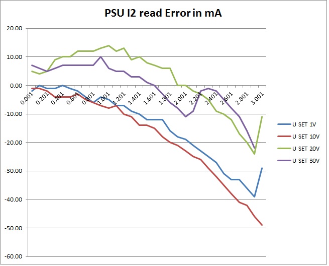
 Download here the measurement datas
|
|
|
|
|