Menu
Description
Keyboard and DC/DC board
RF & PHONE decoder board
Cabling
Previous menu
Historic and new
Home
|
|
RADIO and PHONE DECODER BOARD
|
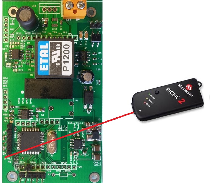
This board allows the decoding of the informations on the phone line (caller and dialer indentifiants) also the decoding of the radio messages coming from temperature sensors.
These messages are sent to the Raspberry through an UART serial interface.
The board is powered in 12V (50mA max)
The board has a CPU PIC 18F4550 from Microchip, it controls :
- A serial UART at 19200 bauds interface to dialog with the main CPU.
- The RADIO informations from a receiver 433MHz (RX433N).
- The on hook and off hook informations of the phone line connected to the FCALLBOX SERVER
- The phone calling messages (CID) originally working with a NJM2211 decoder, has been implemented by decoding inside the CPU, using an analog input of it.
- The phone dialing messages (DTMF), same implemenation as CID.
- The 12V to 5V conversion is done with a DC/DC MP2303 from Monolithicpower
The bill of material below shows only the components to be placed.
Tope side
| Ref |
Description |
Manufacturer / Reference |
| R4,R5,R6 |
Resistor 1KR 5% 0603 |
All brand |
| R21,R22 |
Resistor 10KR 5% 0603 |
All brand |
| R18,R8 |
Resistor 5.6KR 5% 0603 |
All brand |
| R19_2,R53 |
Resistor 22KR 5% 0603 |
All brand |
| R38_2,R9,R10 |
Resistor 100KR 5% 0603 |
All brand |
| R48_2 |
Resistor 13KR 1% 0603 |
All brand |
| R49_2 |
Resistor 68KR 1% 0603 |
All brand |
| R3,R17 |
Resistor 0KR 5% 0603 |
All brand |
| R23 |
Resistor 330R 5% 0603 |
All brand |
| R12 |
Resistor 330KR 5% 0603 |
All brand |
| R16,R51,R52 |
Resistor 1MR 5% 0603 |
All brand |
| C31_2,C32_2,C18,C12,C30,C41 |
Capacitor 100nF 16V X7R 10% 0603 |
All brand |
| C38_2 |
Capacitor 10nF 16V X7R 10% 0603 |
All brand |
| C36_2,C40_2,C42 |
Capacitor 10uF 16V X5R 1210 |
All brand |
| C35_2,C34_2 |
Capacitor 22uF 6.3V X5R 0805 |
All brand |
| C1 |
Capacitor 4.7uF 16V X5R 10% 1206 |
All brand |
| C20 |
Capacitor 100uF 16V traversant pas 2.54mm |
All brand |
| C10,C11 |
Capacitor 220nF 100V X7R1206 |
All brand |
| L1 |
inductor 2.2mH 100mA min 8x8 |
BOURNS - RLB9012-222KL or equivalent |
| L3_2 |
inductor 15uH 2.6A min |
WURTH ELEKTRONIK 74404084150 or equivalent |
| C10,C11 |
line transformer |
ETAL / P1200 |
| J2 |
Connector male 1x6 pitch 2.54mm |
All brand |
| Test point RX TX 0V SD SC TP32 TP33 |
Connector male 1x5 pitch 2.54mm |
All brand |
| J7 |
connector 2 points pitch 5.08mm |
WEIDMULLER 1760490000 or equivalent |
| C20 |
Converter isolated 12V to 5V 1W or 2W |
RECOM / RS-1205S |
| U6 |
optocoupler SHF6156 CMS |
All brand |
| X1 |
XTAL 24MHz 30/30/40/12pF CMS 5x7 mm |
EUROQUARTZ / 1640921 or equivalent |
| U3 |
Integrated circuit 18F4550 TQFP 44 |
Microchip / PIC18F4550-I/PT |
| U2 |
Integrated circuit comparator LM211 SO8 |
All brand |
| U14 |
Integrated circuit AOP LM358 SO8 |
All brand |
| U8_2 |
Integrated circuit MP2303 SO8 |
MPS (Monolithic Power System) / MP2303ADN-LF |
| D5 |
Diode BAS20 |
All brand |
| D4 |
Diode TVS 5V like SDC05 |
NXP ref PESD5V0L1BA |
| D6 |
diode bridge MD5S |
RECTRON ref MD5S |
| MODULE RADIO |
Radio module 433MHz RX433N |
RX433N by Velleman or other |
|
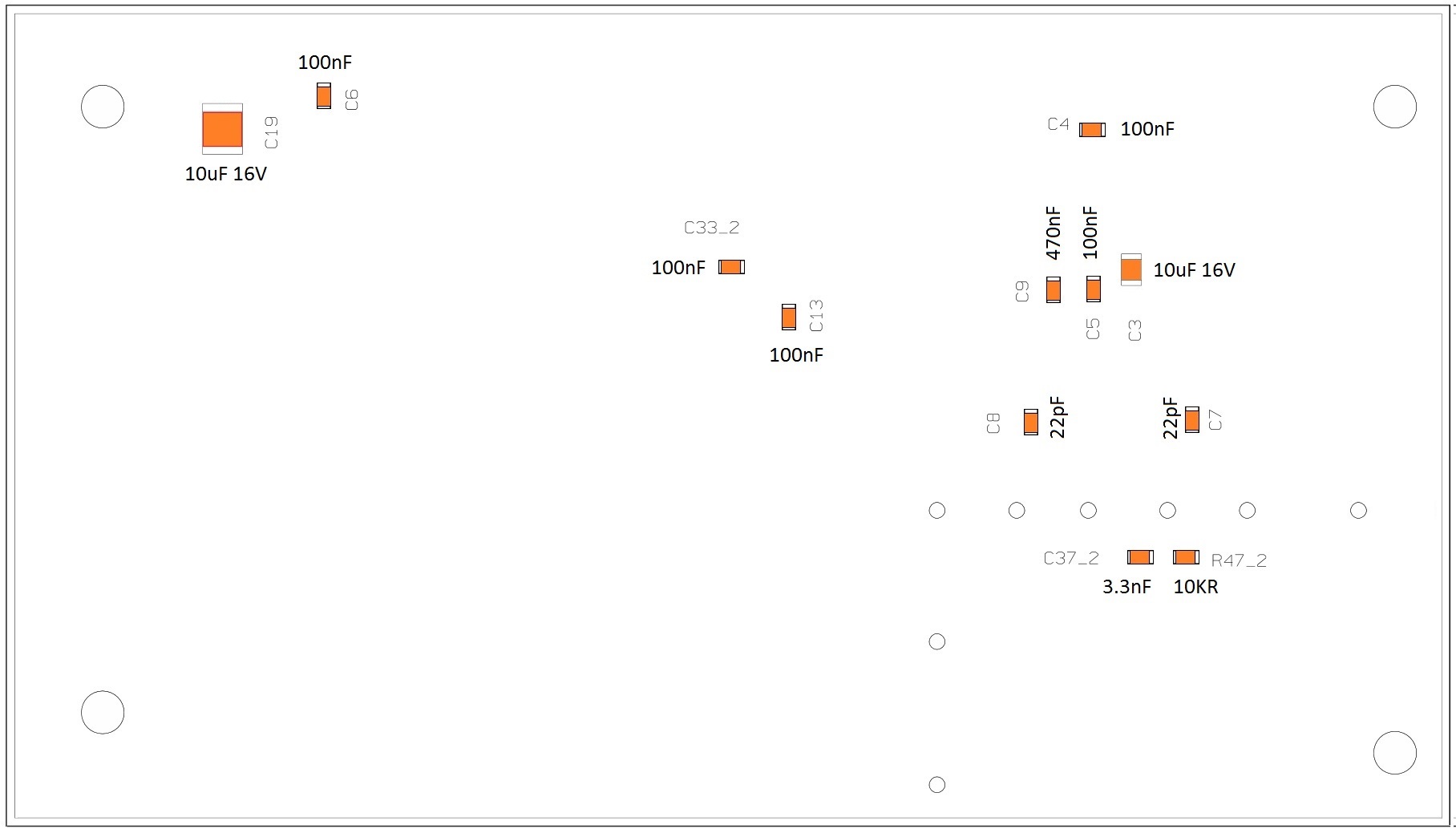
bottom side
| Ref |
Description |
Manufacturer / Reference |
| C7,C8 |
Capacitor 22pF 50V COG 0603 |
All brand |
| C9 |
Capacitor 470nF 16V X7R 10% 0603 |
All brand |
| C4,C5,C6,C13,C33_2 |
Capacitor 100nF 16V X7R 10% 0603 |
All brand |
| C37_2 |
Capacitor 3.3nF 16V X7R 0603 |
All brand |
| C3 |
Capacitor 10uF 16V X7R 0805 |
All brand |
| C19 |
Capacitor 10uF 16V X5R 1210 |
All brand |
| R47_2 |
Resistor 10KR 5% 0603 |
All brand |
|
- The board which has 51x91mm dimensions is a part of the PCB F00105 with 100x100mm dimensions.
- So, you need to cut it to get the PCB of the Display board.
Below the picture of the location of the cut on the PCB F00105

Download the manufacturer files here
The board has components on the two faces.
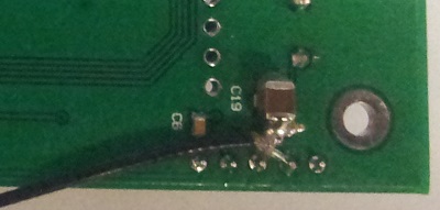
WARNING : a modification has to be applied, see next section
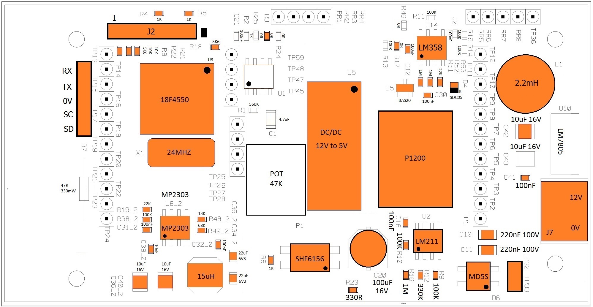
Top view
Bottom views
Top view without radio module (U1 .. do not be populated, follow the BOM)
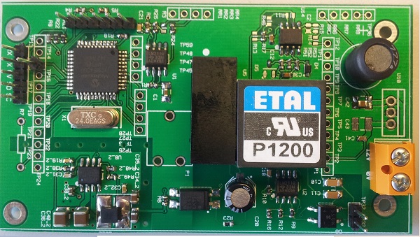
Top view with radio module (U1 .. do not be populated, follow the BOM)

Bottom view without radio module

Bottom view with radio module
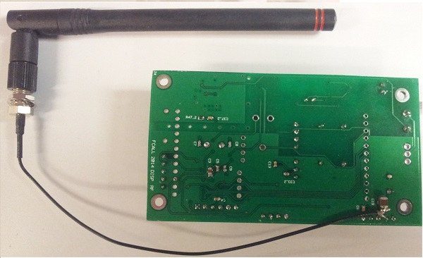
Antenna cabling detail
Download the top view here in PDF format
Download the bottom view here in PDF format
|