|
|
MenuDescription Top Menu Home |
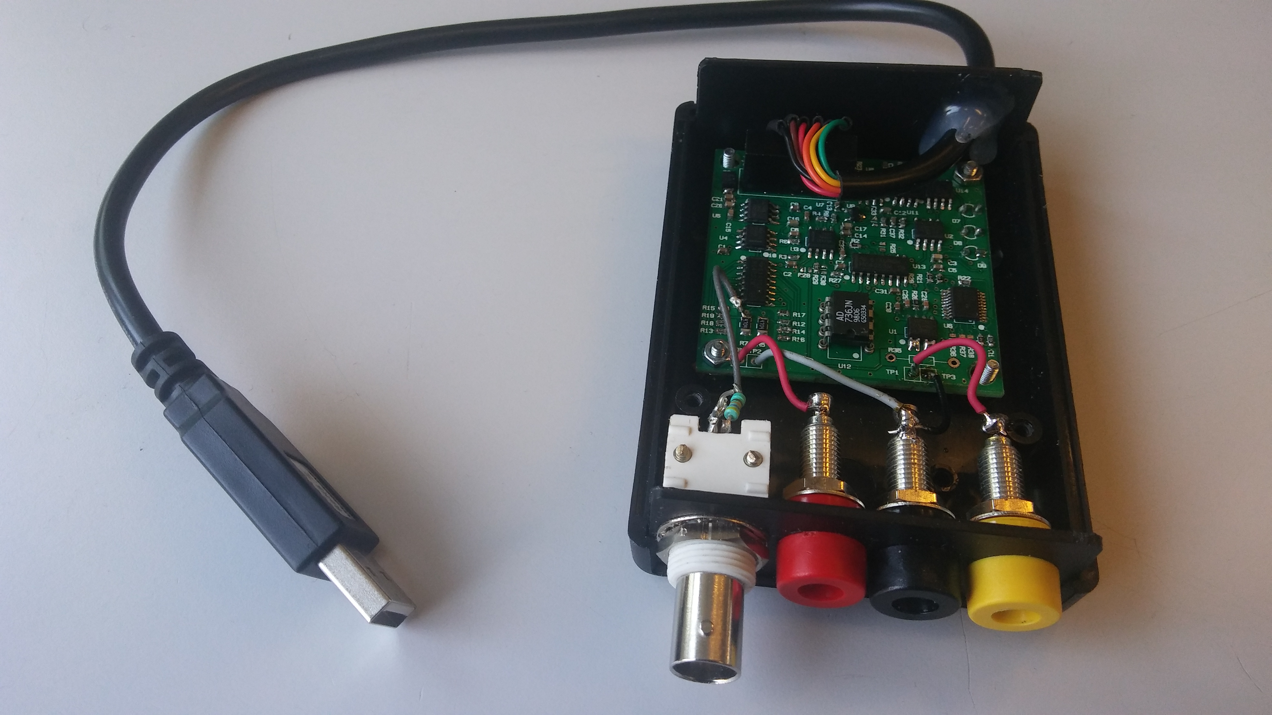
This small module is a voltmeter and amperemeter high precision DC and AC RMS. We can use up to 8 modules at the same time on a PC (only one on a mobile) It has no display and it has to be used with a PC or a mobile (Android), it's power comes from the USB port and the module is fully isolated from the PC with no risk of electric shock (1500V insulation). The characteristics are : - Voltmeter auto-range , auto polarity DC and AC true RMS (range can be changed by resistor adjustment).
Légende : Green < 1dB, blue < 3dB, Red > 3dB - Amperemeter 5A or more or other by hardware configuration, DC or AC true RMS (but the voltmeter is not available in current AC mode)
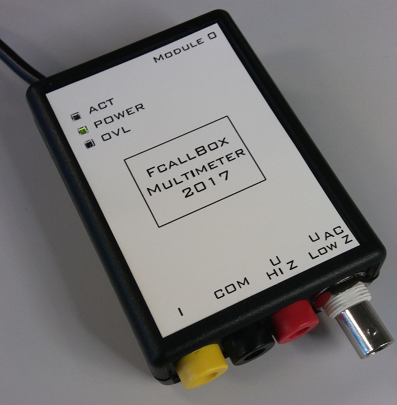
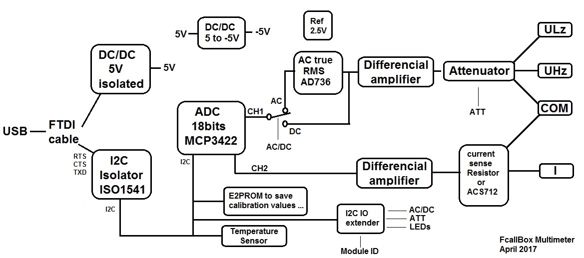
- Temperature sensor for measurements tracability. - Note : plug COM is common for U and I. - Calibration by PC. - The PC software has a socket server to allow remote control of the module (for eg to script measurements or to use remotly the module by a mobile...) - dimensions PCB : 100x50mm SummaryBLOCK DIAGRAM
Some explainations about the module operations : In fact the module is a big I2C USB_deviceice : -The main of the module an ADC 18bits MCP3422 2 channels, a little bit slow (3.75s/S) but with high accurency. -A temperature sensor TCN75A, to trace the temperature close to ambiant during the measurements. -An E2PROM 24C32 to record the calibration value an other parameters, this allow to have the module autonomous (no data recorded on the PC, mobile...). -An IO extender PCF8574 to set the attenuater, AC/DC mode, the leds. also to read the module ID number (0 à 7), requested to use several modules on the same PC. The voltmeter input stage has an 5 ranges attenuator (74HC4052) (3 more by using MCP3422 PGA) The input is protected by diodes BAS416 with very low leakage current and very low change on temperature, this allows stable measurement versus temperature variations. The input impedance is 4.7M for the 4 hightest range and 10M forthe others, for the AC input, it is 47K (but we could also use HZ input (4.7 .. 10MR) but this will decrease the band with. the AOP are OPA2197 (Rail-to-Rail Input Output, Low Offset Voltage Op Amp). A mux 74HC4053 switchs some functions, AC/DC mode, also AC current, but not implemented by the software. For AC, BF (max 200KHz), I have used a true RMS AD736, not really precise but enough, the measurement can be displayed in Vrms, dBm, dBu, dBV, mW (the impedance reference can be choosen (by soft). For the current measurement we have 2 choices : -A ACS712, current sensor 5A (or 20 or 30A but attention about the wiring) with a low resistance 1,2mR and a precision not excelent (see results at the end of the page). -With resistor, here 2R for 1A max, but you can use other value and change it in the soft. The module is insulated from the PC, that means that the voltage and current are fully isolated from the USB,so no risk of electric shock for the PC or mobile . The insulation is done with a ISO1541 for I2C and a DC/DC isolated RECOM which converts the 5V of the USB in 5V isolated for the module. Note that the I2C is generated from the USB to UART série TTL (3.3V or 5V), I use the signals RTS, CTS and TXD to do the I2C soft. And there are 3 leds, power = 5V presence , OVL = overload (voltage or current), ACT = blink when software is active. Schematic
Download the schematic here Note : R17 and R19 are 9K1 and not 47K. Bill of materialThe BOM below shows the version 5A AND 1A, refer to the note below to know what must be implemented.
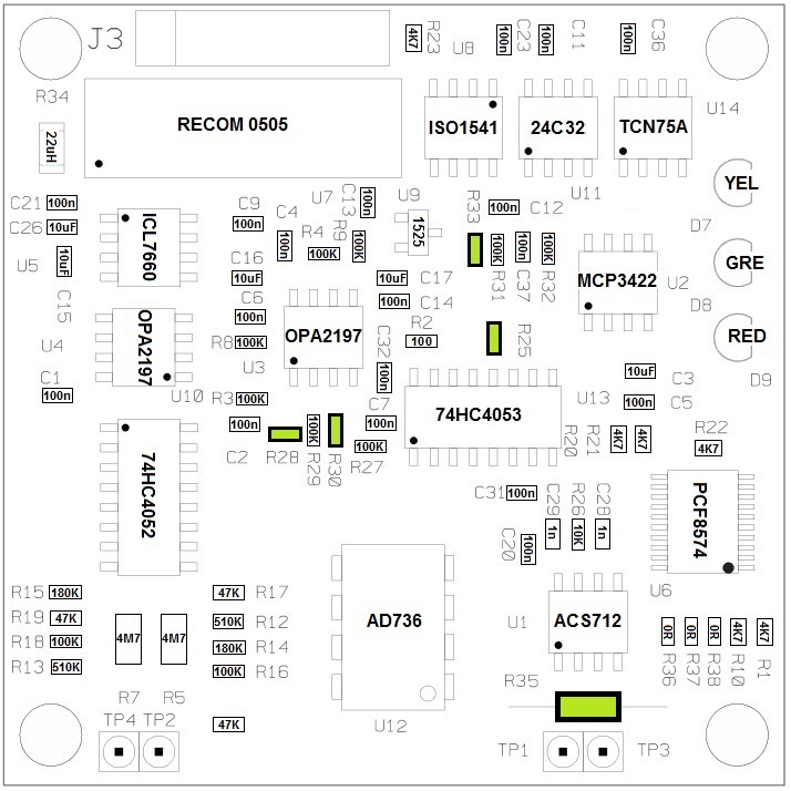
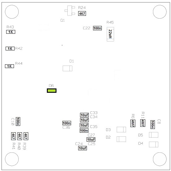
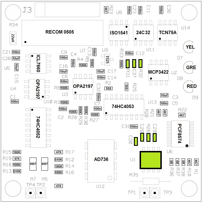
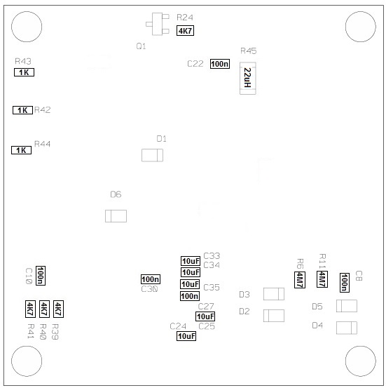
Attention R34 and R45 are inductor and not resistor, this is to reduce the noise generated by the DC/DC For the version 5A or more, do not mount : R25,R28,R30,R33,R35,D6 For the version 5A or more you must use ACS712ELCTR-05B-T for 5A, ACS712ELCTR-20A-T for 20A or ACS712ELCTR-30A-T for 30A. For the version 1A or less, do not mount : U1,C20,C28,C29,R26,R31,R32,C37 As written above, we can have up to 8 modules on a PC, they are numbered 0 to 7 NE : not mounted, 0R : resistor 0R 0603 mounted.
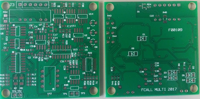
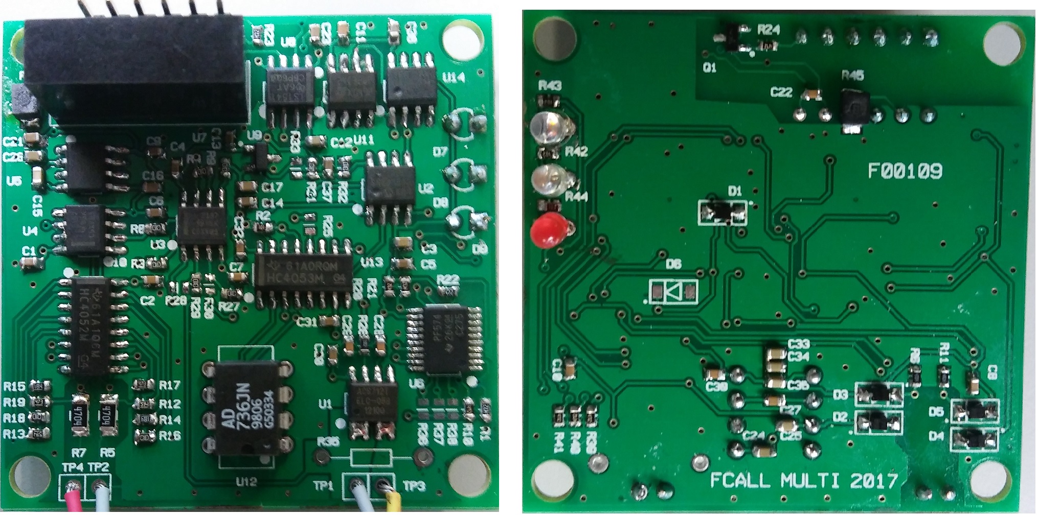
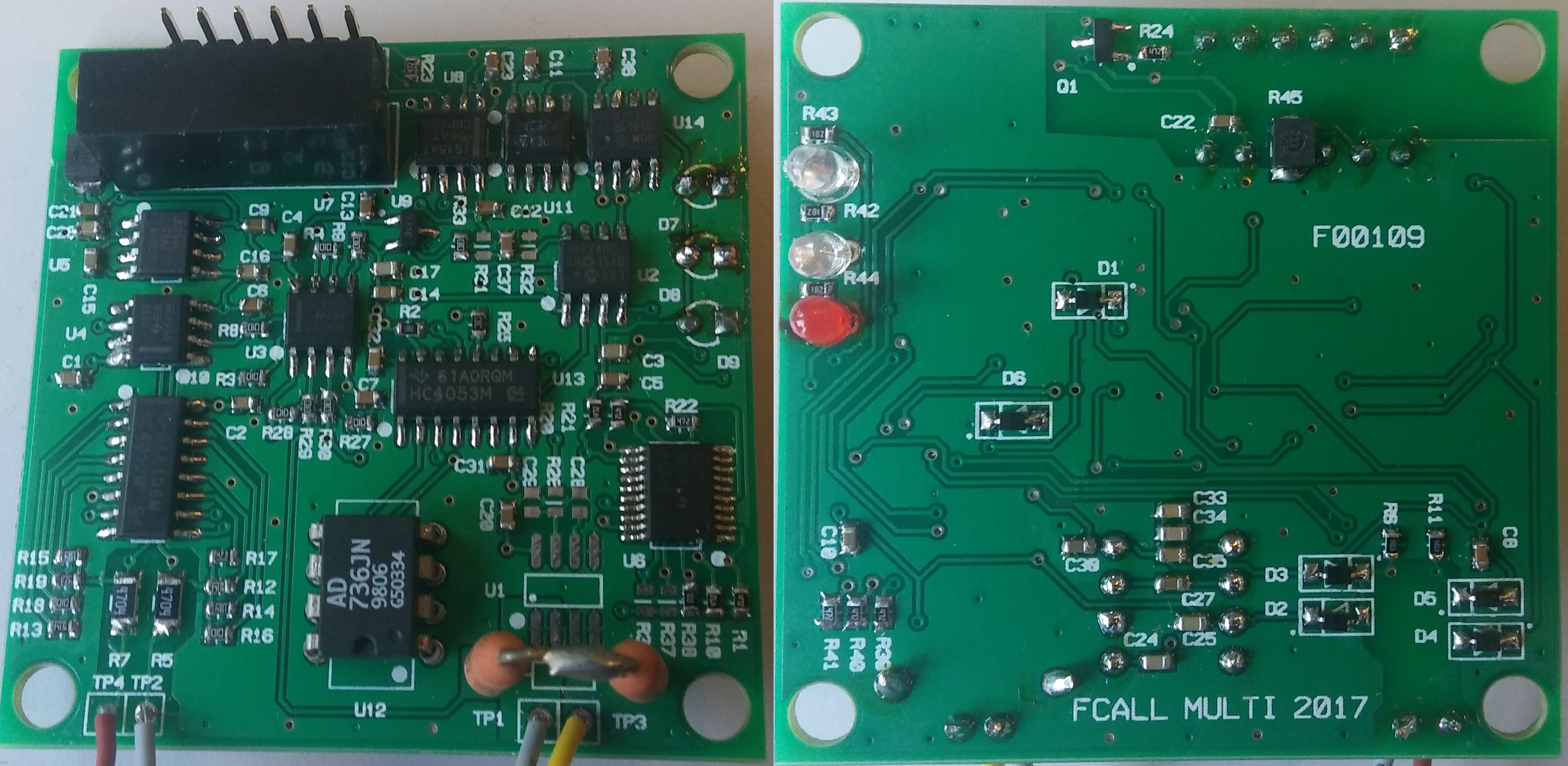
PCBThe dimensions of the board are 50x50mm. Below the picture of the F00109 PCB
AssemblyThe board has components on both faces. Do not mount component in green according to the version. Attention R34 and R45 are inductor and not resistor, this is to reduce the noise generated by the DC/DC Attention : R17 et R19 are 9K1 and not 47K.
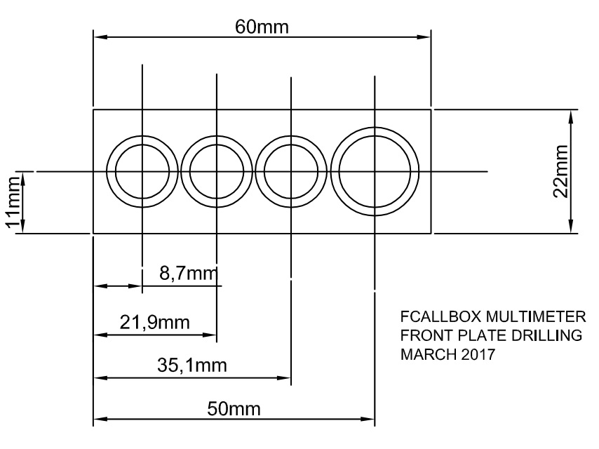
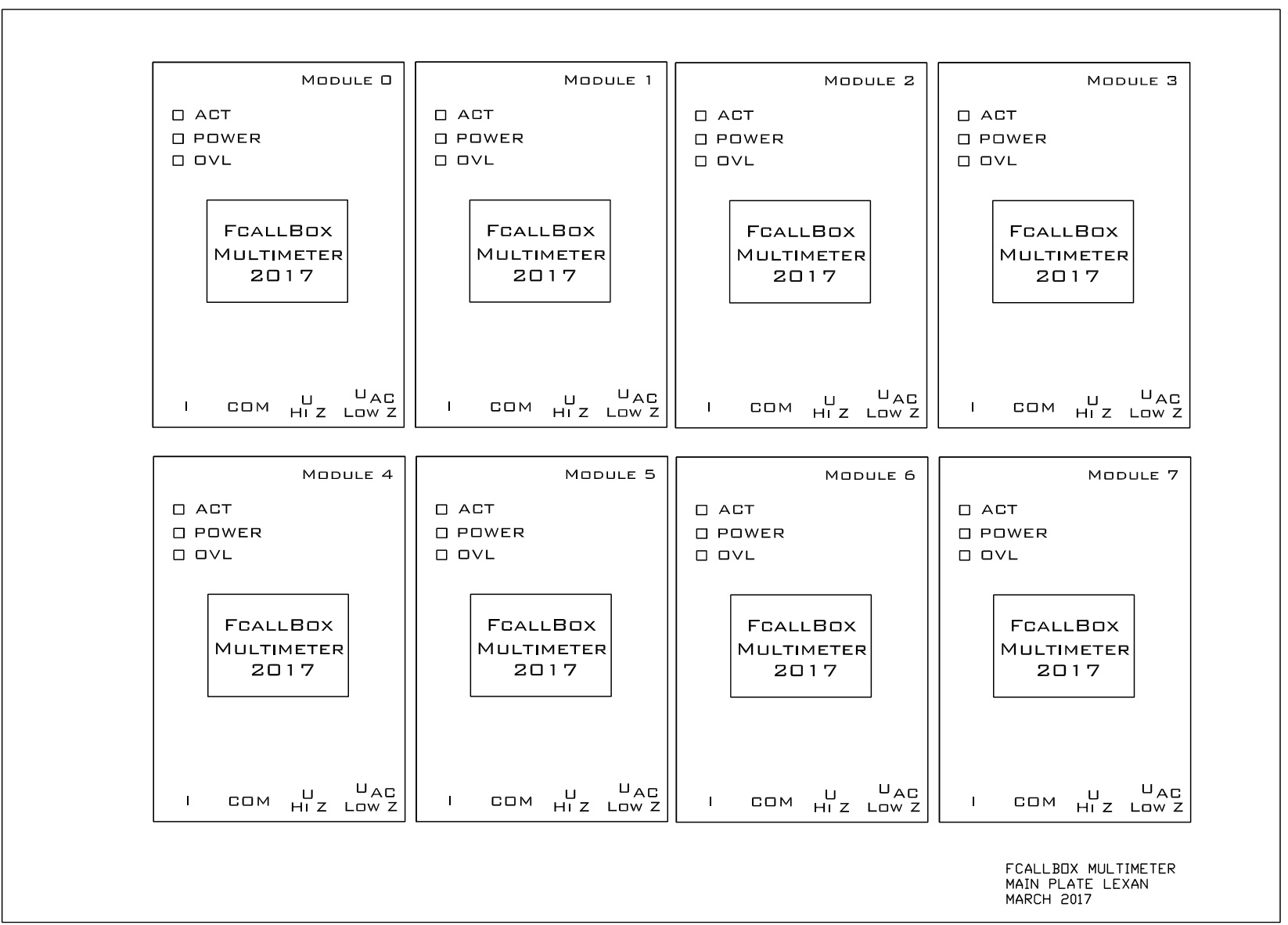
Mechanical
For the face silkscreen, my method consists to print it on a picture paper, then to cut the oppertures and place few adhesive thin tapes at several places,and to place the paper on it. Attention : mount the 4 screew + nutes of the box before placing the paper.
CASING MOUNTING AND WIRINGFor the box, you need : - A box Hammond Manufacturing 1593LBK - A red femal plug type Pomona 1581-2 - A black femal plug type Pomona 1581-0 - A yellow femal plug type Pomona 1581-4 - A Coaxial BNC connector for pannel mounting - A cable USB to TTL FTDI TTL-232R-5V-WE or TTL-232R-3V3-WE Mounting : - Fix the board with 4 screews and nuts. - Cut the FTDI cable at the lenght you want and wire it on J3 connector. - wire the following : - TP4 on red plug (U+ High Z). - TP2 on black plug (COM). - TP3 on black plug (COM). - TP1 on yellow plug (I). 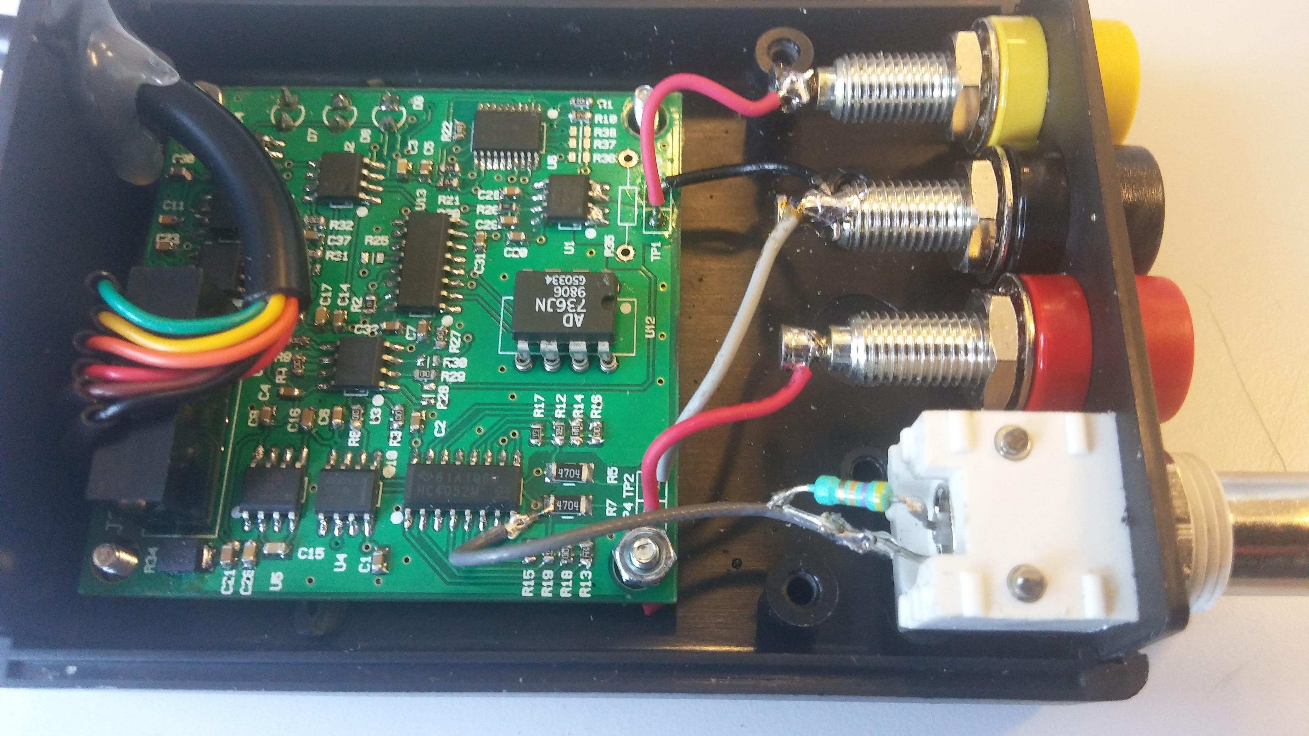
- I have also added a low impedance input for the AC voltage, you have to had a shielded cable with a 39K in serie with a 100nF 100V as bellow : 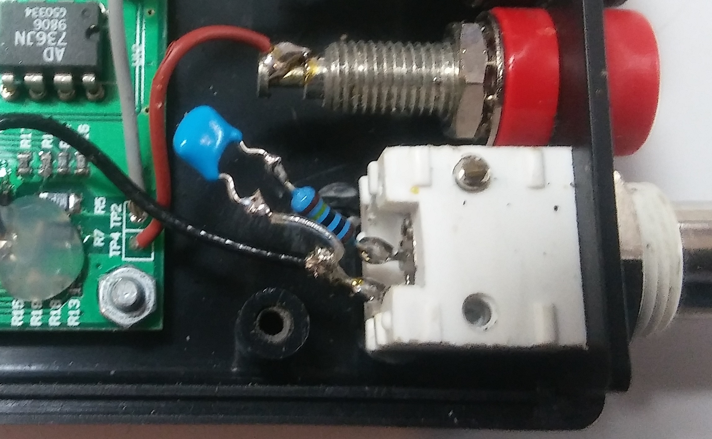
Power OnPlug the module on a USB port of a PC, the led POWER must be light on in green. 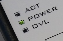
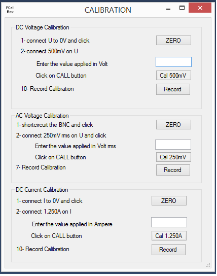
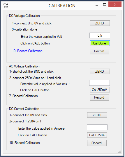
SOFTWARE UNDER WINDOWSThe application software allows to control the module through USB. But it is also needed to calibrate the module. Download here the file and uncompress it in a folder then launc FcallBoxMULTIMETERV200.exeThe software scans all the ports COM of the PC, if a port is available, it try to record a patern into the flash of the module, if the read back is ok, it knows that it has identified a module. Then it reads the USB_deviceice ID (0 to 7) which it displays in the TOP bar. On the screen below, on top voltmeter, at the middle Amperemeter, in bottom remote control and buttons RECORD and CALIBRATION.
For the Voltmeter DC, details below : - Auto correspond to auto range, the soft change the calibre itself, in high if overload, in low if the value is lower than 90% of the max of the calibre inferior. - 500mV ... 1KV calibre used, in non auto mode, you can change the calibre by clicking on one of them. For the amperemeter, details below for the resistance version : - Auto correspond to auto range, the soft change the calibre itself, in high if overload, in low if the value is lower than 90% of the max of the calibre inferior. - 0.125A ... 5A calibre used, in non auto mode, you can change the calibre by clicking on one of them. - Zero used to force Zéro for all the calibres which it scans, valable only for the mode AC/DC selected.For the Voltmeter AC, click on AC/DC the same functions than DC are applicables :
Below amperemeter in mode 5A The change is done by clicking on the buttons on the Current Setup window, the resistor value can be set only in R mode. You can click on the button RECORD to save the change of mode, attention, it records always all the changes (calibration)...
Click on CAL to launch the calibration, follow the instructions, once the calibration is done, the button used goes in green. Always do a Zero before calibration (attention, the ZERO calibre at 0 only the mode selected (AC DC AMP)). Do a Record, attention, it records all the calibrations.
QUALIFICATION and measurements
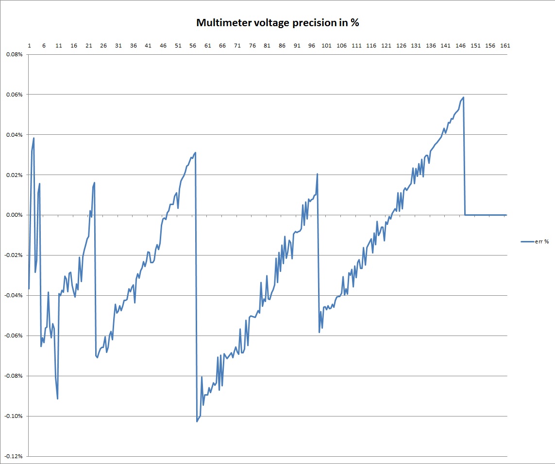
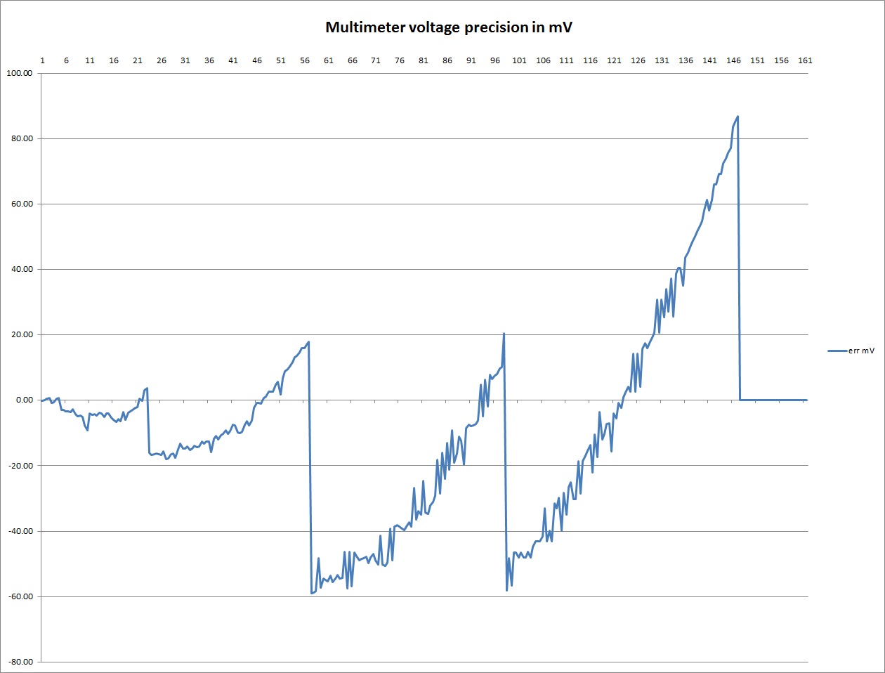
Below the voltage measurements comparison with a HAMEG 8012 between 0.5V to 150V in auto range mode by 0.5V step :
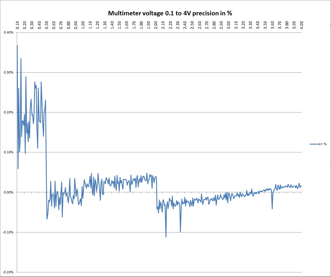
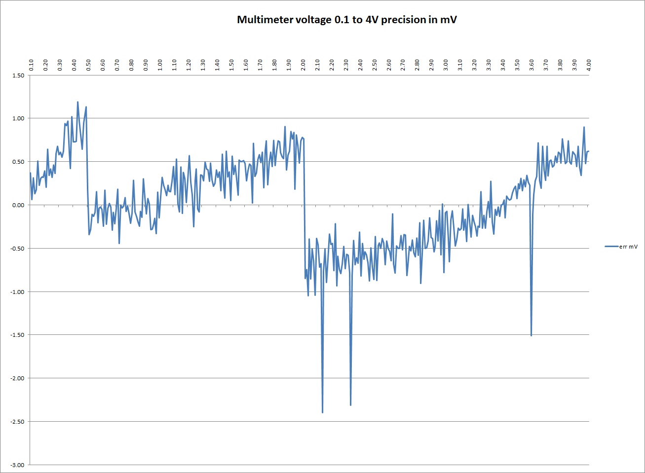
Download here the details with the datas array Below the voltage measurements comparison with a HAMEG 8012 between 0.1V to 4V in auto range mode by 10mV step :
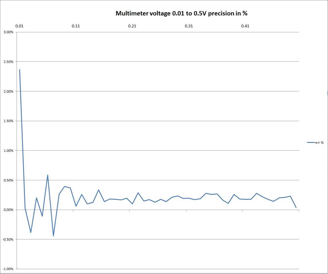
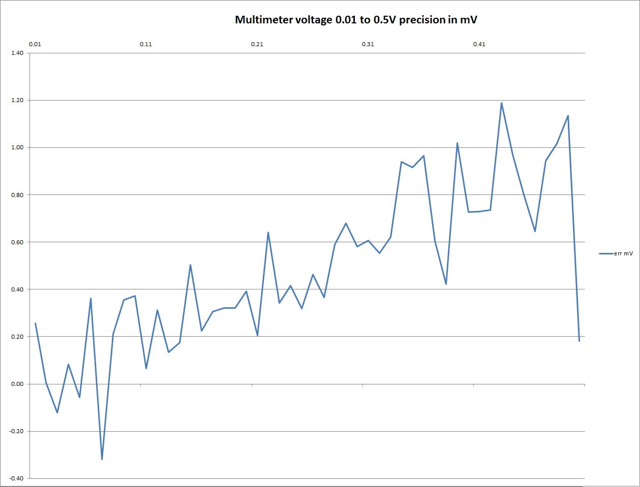
Download here the details with the datas array Below the voltage measurements comparison with a HAMEG 8012 between 0.01V to 0.5V in auto range mode by 10mV step :
Download here the details with the datas array
Below the voltage measurements comparison with signal generated by an Agilent 33250A at 1Vrms from 1KHz to 500KHz by 1KHz step :
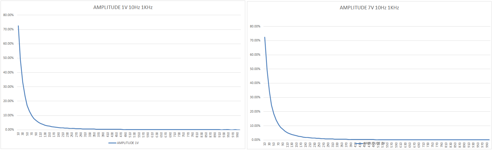
Caption : Green < 1dB, blue < 3dB, Red > 3dB measurements comparison with signal generated by an Agilent 33250A from 10Hz to 1KHz for 10mV, 100mV, 1V and 7VRms : 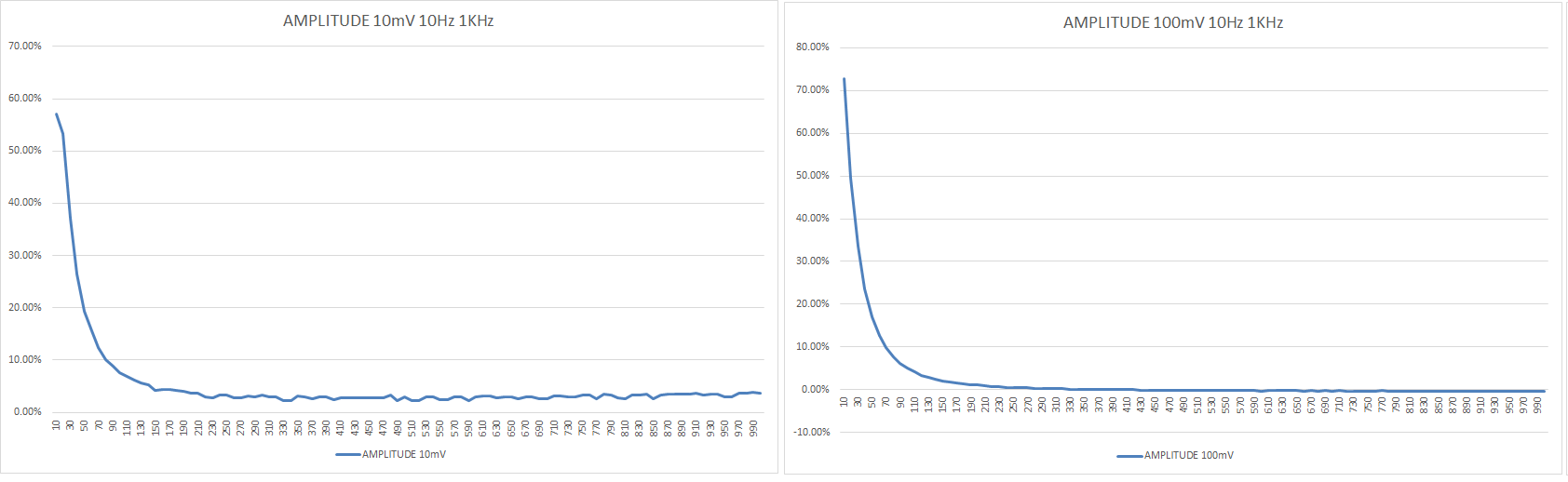
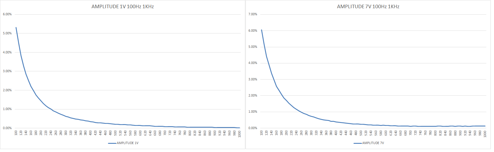
measurements comparison with signal generated by an Agilent 33250A from 100Hz to 1KHz pour 10mV, 100mV, 1V and 7VRms : 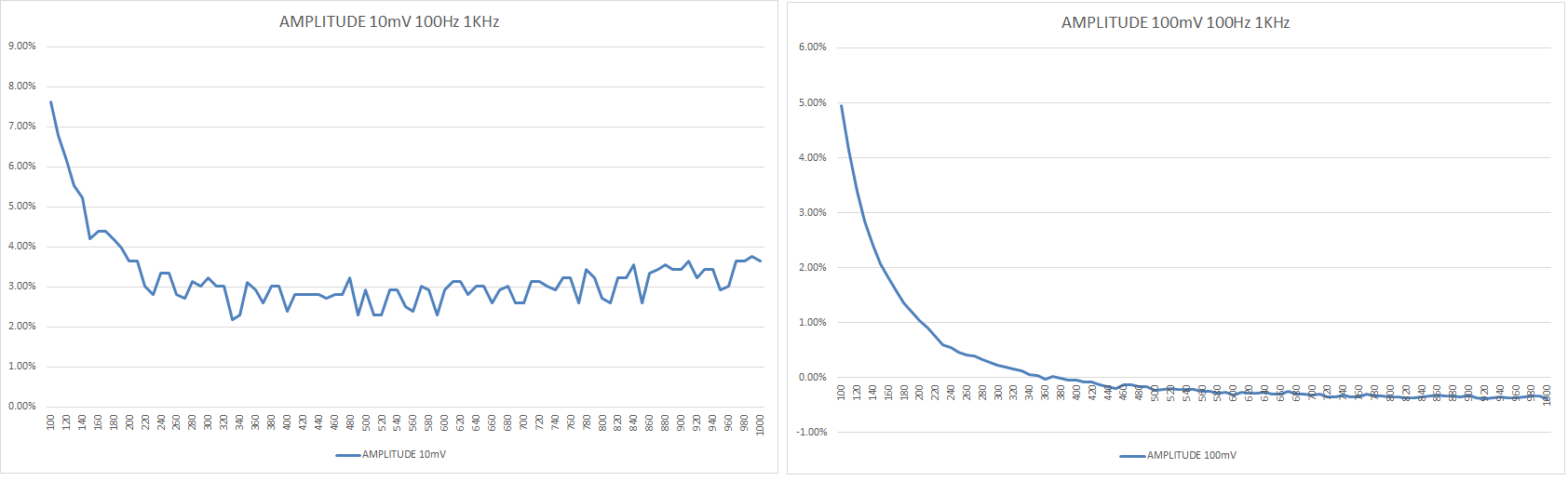
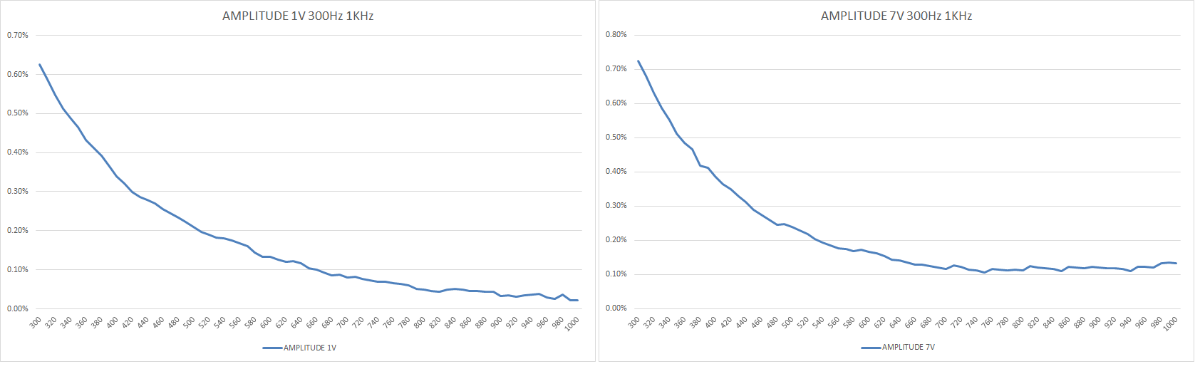
measurements comparison with signal generated by an Agilent 33250A from 300Hz to 1KHz pour 10mV, 100mV, 1V and 7VRms : 
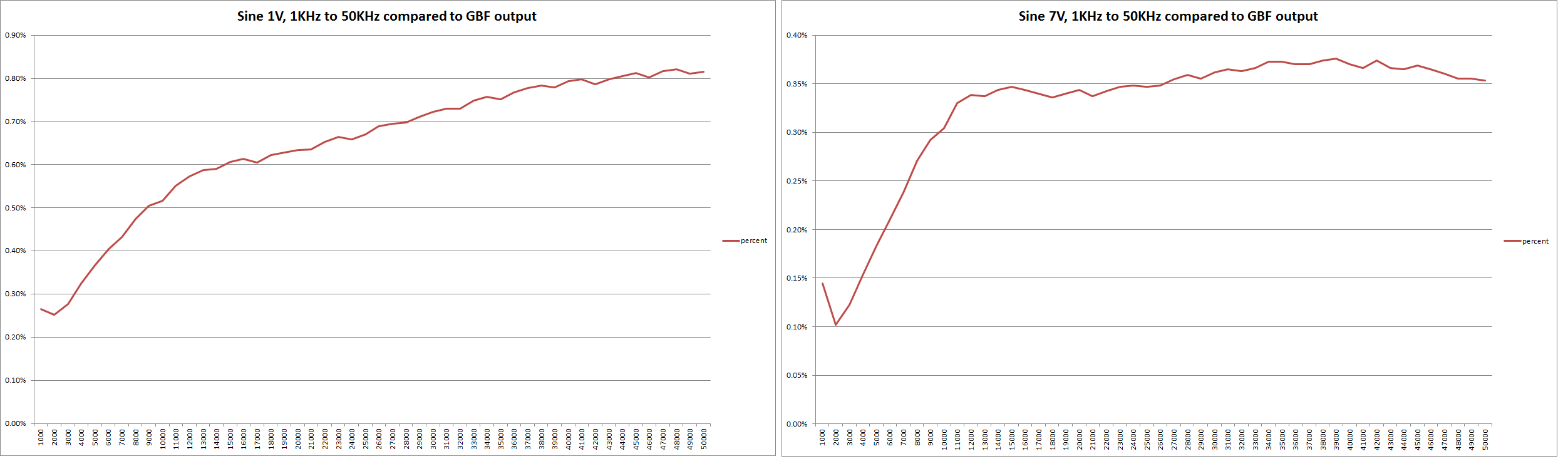
Légende : Green < 1dB, blue < 3dB, Red > 3dB measurements comparison with signal generated by an Agilent 33250A from 1KHz to 50KHz for 100mV, 1V and 7VRms : 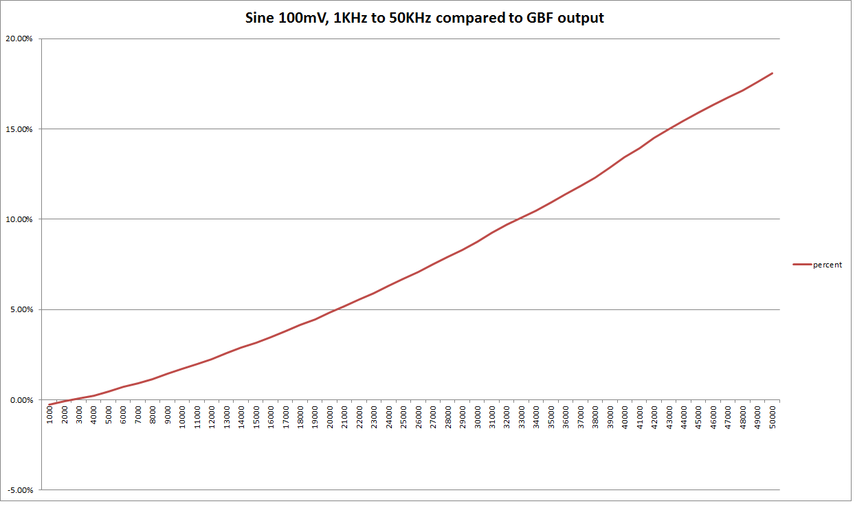
measurements comparison with signal generated by an Agilent 33250A from 1KHz à 300KHz for 100mV, 1V and 7VRms : 
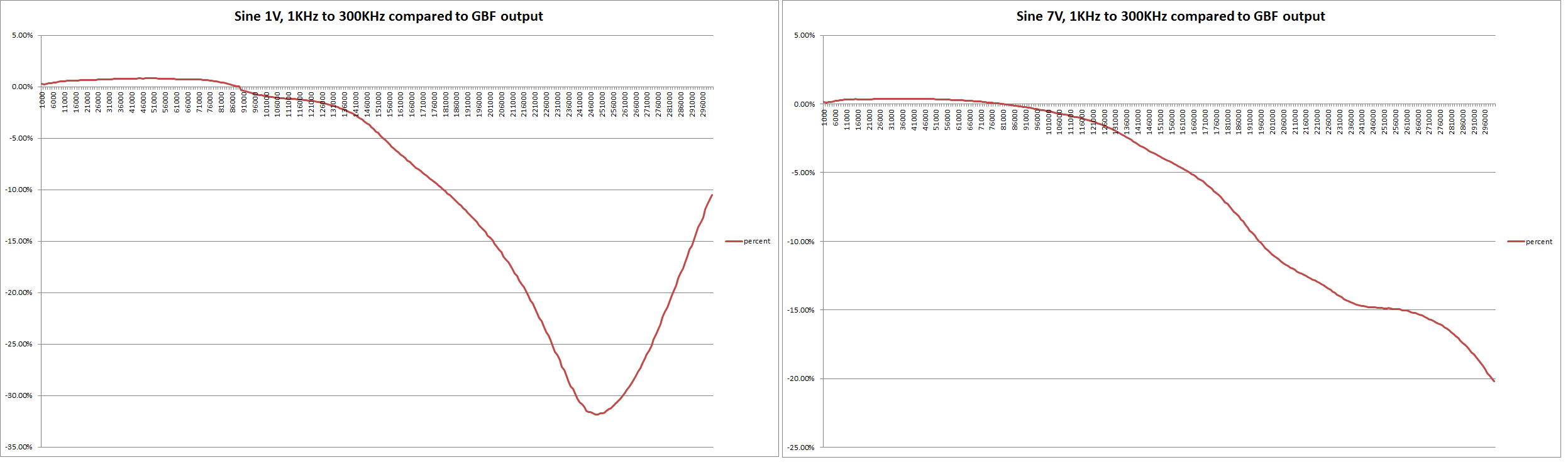
Légende : Green < 1dB, blue < 3dB, Red > 3dB measurements comparison with signal generated by an Agilent 33250A for 1KHz from 10mV to 7VRms : 
measurements comparison with signal generated by an Agilent 33250A for 10KHz from 10mV to 7VRms : 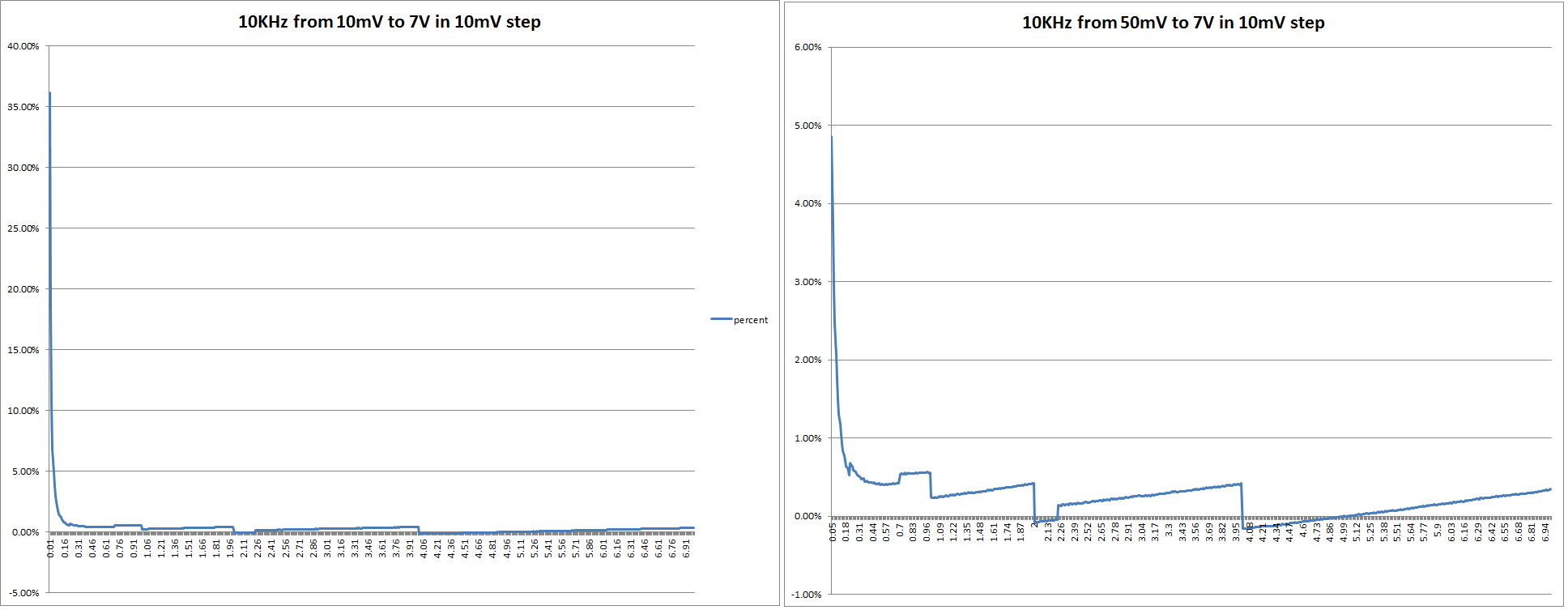
measurements comparison with signal generated by an Agilent 33250A for 22KHz from 10mV to 7VRms : 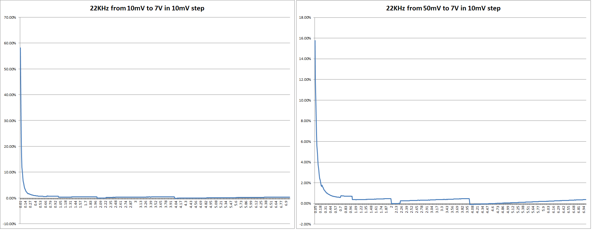
measurements comparison with signal generated by an Agilent 33250A for 50KHz from 10mV to 7VRms : 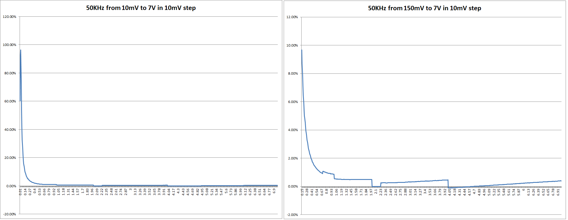
measurements comparison with signal generated by an Agilent 33250A for 100KHz from 10mV to 7VRms : 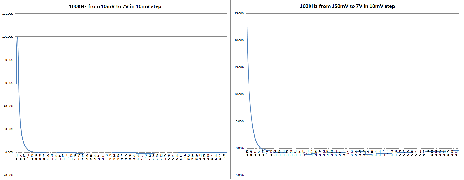
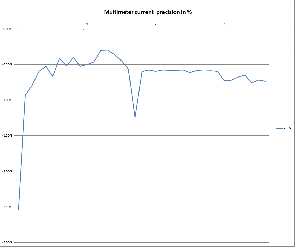
Below the current measurements comparison with a HAMEG 8012 between 0 to 3.7A in auto range mode by 0.1A step :
Download here the details with the datas array
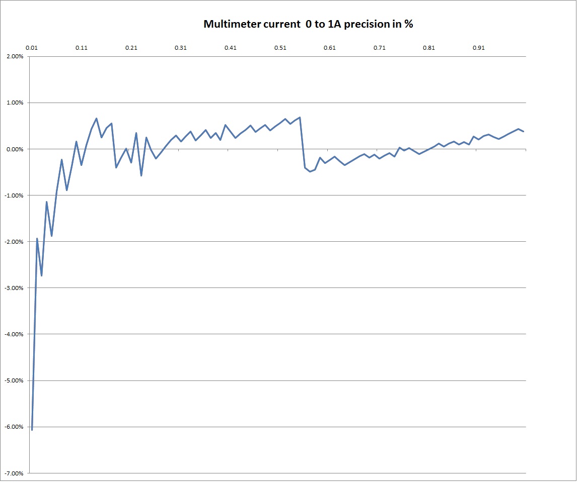
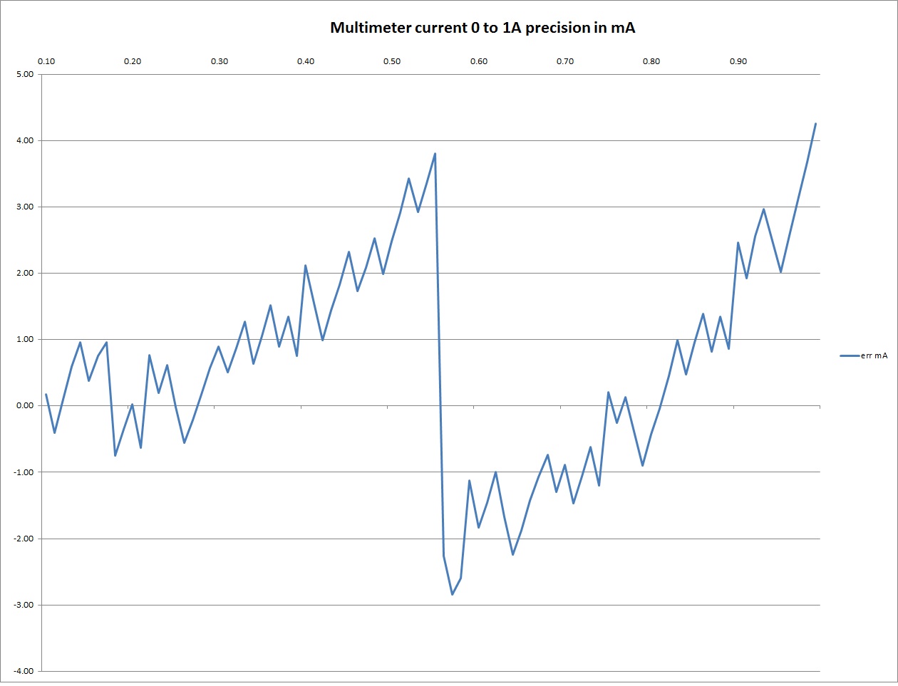
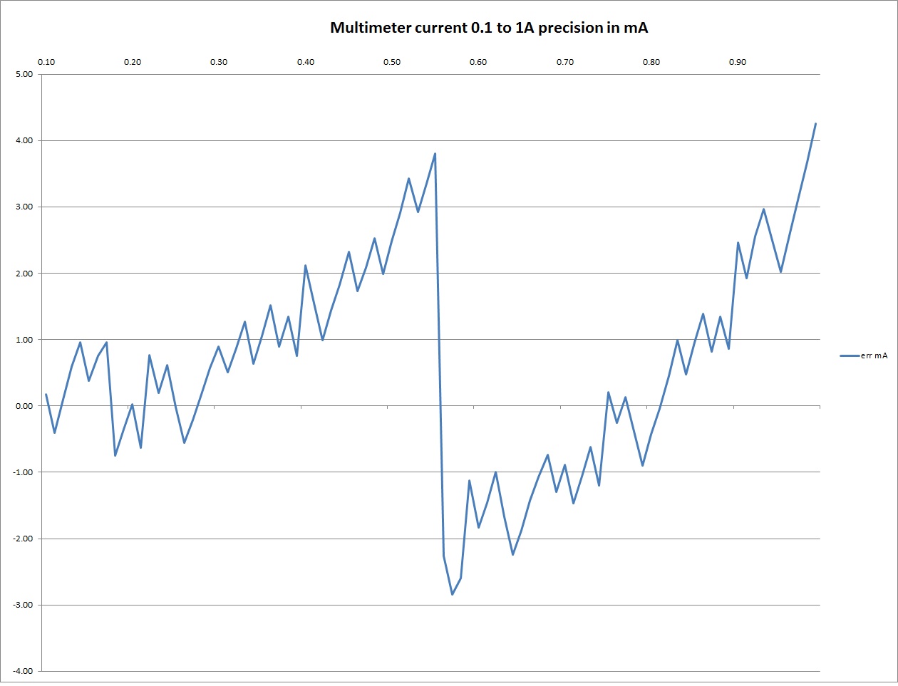
Below the current measurements comparison with a HAMEG 8012 between 0 to 1A in auto range mode by 0.1A step :
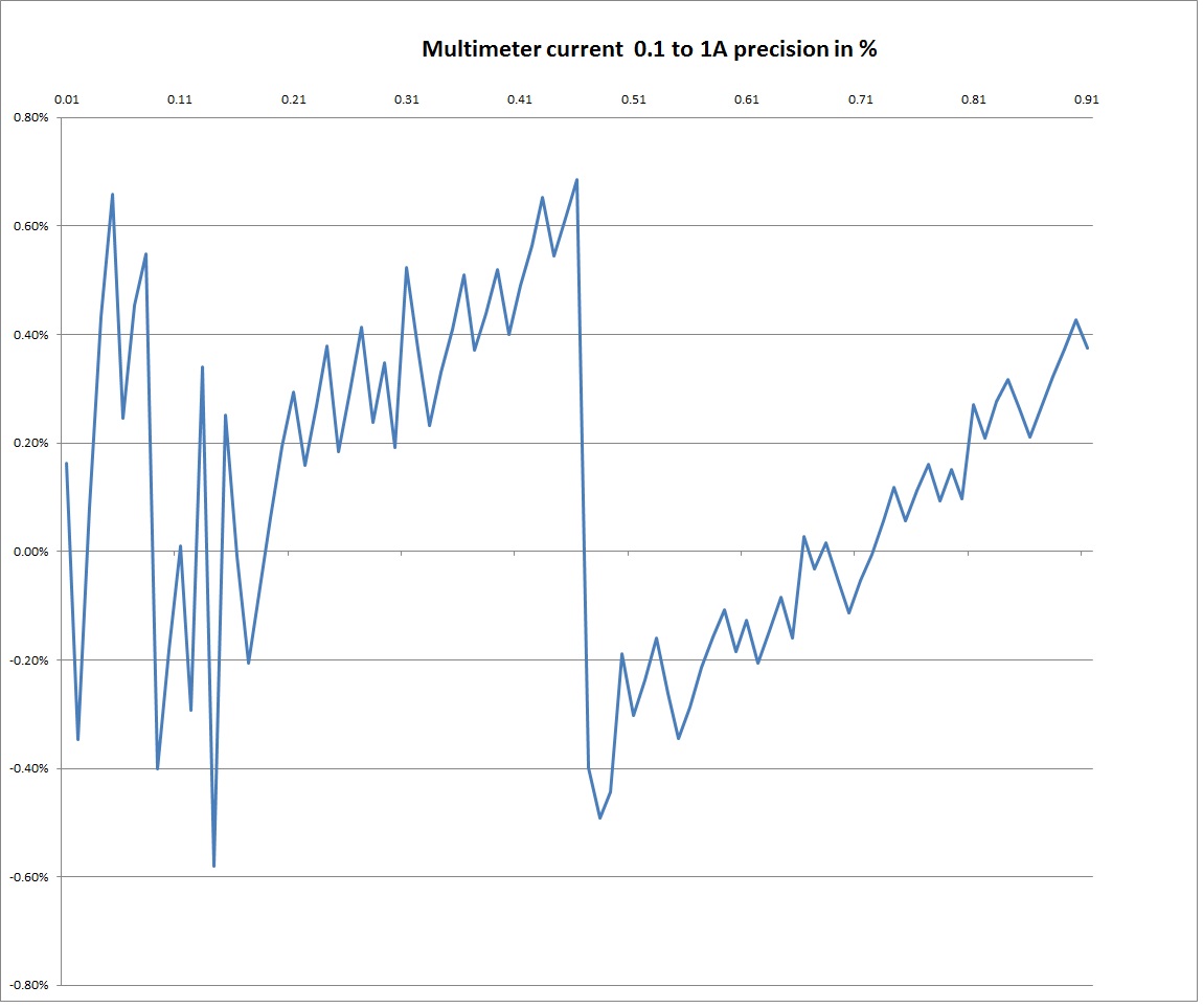
Below the current measurements comparison with a HAMEG 8012 between 100mA to AA in auto range mode by 0.1A step :
SOFTWARE UNDER WINDOWS : REMOTE CONTROLThe application can be remote controled throug a link Socket Server-Client The field IP and Port must be configured, use 127.0.0.1 if the remote control software is on the same PC The available commands are listed below : VOLT Commandes : SET_VOLT_AUTO_ON : set auto range ON for VOLT, return OKSET_VOLT_AUTO_OFF : set auto range OFF for VOLT, return OK SET_VOLT_AC_MODE : set VOLT AC, return OK SET_VOLT_DC_MODE : set VOLT DC, return OK SET_VOLT_AC_RMS : set VOLT AC Rms, return OK SET_VOLT_AC_DBM : set VOLT AC dBm, return OK SET_VOLT_AC_DBV : set VOLT AC dBV, return OK SET_VOLT_AC_DBU : set VOLT AC dBu, return OK SET_VOLT_AC_MW : set VOLT AC mW, return OK SET_VOLT_RANGE_1 : set VOLT RANGE 1 (500mV in DC), return OK SET_VOLT_RANGE_2 : set VOLT RANGE 2 (1V in DC), return OK SET_VOLT_RANGE_3 : set VOLT RANGE 3 (2V in DC), return OK SET_VOLT_RANGE_4 : set VOLT RANGE 4 (4V in DC), return OK SET_VOLT_RANGE_5 : set VOLT RANGE 5 (20V in DC), return OK SET_VOLT_RANGE_6 : set VOLT RANGE 6 (50V in DC), return OK SET_VOLT_RANGE_7 : set VOLT RANGE 7 (100V in DC), return OK SET_VOLT_RANGE_8 : set VOLT RANGE 8 (1KV in DC), return OK SET_VOLT_AC_IMPEDANCE value : set VOLT AC impedance : eg SET_VOLT_AC_IMPEDANCE 600, return OK SET_VOLT_DC_ZERO : compute DC ZERO calibration, return OK SET_VOLT_AC_ZERO : compute AC ZERO calibration, return OK GET_VOLT_VALUE : return VOLT value in mV dBm ... eg : -001.0627 or -15.860 ... GET_VOLT_UNIT : return VOLT unit : mV dBm ... eg : mV or dBU ... CURRENT Commandes : SET_CURRENT_AUTO_ON : set auto range ON for CURRENT, return OKSET_CURRENT_AUTO_OFF : set auto range OFF for SET_CURRENT_RANGE_1, return OK SET_CURRENT_RANGE_1 : set CURRENT RANGE 1 , return OK SET_CURRENT_RANGE_2 : set CURRENT RANGE 1 , return OK SET_CURRENT_RANGE_3 : set CURRENT RANGE 1 , return OK SET_CURRENT_RANGE_4 : set CURRENT RANGE 1 , return OK SET_CURRENT_DC_ZERO : compute DC CURRENT ZERO calibration, return OK GET_CURRENT_VALUE : return CURRENT value in mA : 2581.2131 GET_CURRENT_UNIT : return CURRENT unit : mA Others Commandes : RECORD : record actual calibration and setting in E2PROM of the module, return OKGET_TEMPERATURE return temperature of the module eg 33.0°C
|
|
|
|
|